Showing posts with label process control. Show all posts

New Pulsar R86 Non-contact Radar Level Transmitter From Magnetrol

non-contact radar level transmitter
Magnetrol's new non-contact radar level transmitter,,
Pulsar R86
Courtesy Magnetrol
Level measurement is a part of countless industrial processes and installations. Accurate measurement of contained solids or liquid enhances safety and operational efficiency, both of which contribute to the bottom line.

Magnetrol, globally recognized innovator in flow and level measurement, recently released its latest version of non-contact radar level measuring instruments. The Pulsar R86 transmitter operates in the 26GHz range, delivering a smaller wavelength with improved resolution, smaller antenna, and a narrower beam. Other unique innovations have been incorporated into the instrument to simplify installation and application.

The R86 is suitable for a broad range of applications across almost every industry. On board diagnostics are incrementally advanced to provide best performance and deliver the information needed to maintain proper operation.

The latest information on the Pulsar R86 is included below. Reach out to process measurement specialists and share your measurement challenges and requirements. Combining your own process knowledge and experience with their product application expertise will result in an effective solution.


Myths About Process Switches

general purpose switch for temperature pressure differential pressure
Example of a general purpose switch for industrial use
Courtesy United Electric Controls
We may have developed an obsession with data and information. Understatement, right? Whether a process variable is high or low no longer is satisfactory. We want to know how high, how low, how long, how fast is it changing, and more. In many cases, this is useful information that can be applied toward goals of safety and efficiency. Let us not, however, overlook the possibility that some facets of an operation are best served by that old soldier, the process switch.

Process switches are readily available for temperature, pressure, and differential pressure in ranges to suit almost any application. They are rugged time and field proven devices designed to do one thing extremely well. Process switches will reliably and instantly change the state of their mechanical switch when the process value reaches their setpoint. Once properly installed and set, process switches require little, if any, maintenance and can provide extended periods of reliable service.

United Electric Controls, globally recognized leader in the manufacture of process switches for temperature, pressure, and differential pressure, authored an informative piece that debunks some myths about process switches. The piece is included below and makes interesting reading.

Establishing the best instrumentation and control layout for a process benefits from careful consideration of many factors. Share your requirements and challenges with process measurement and control specialists, combining you own process knowledge and experience with their current product application expertise to develop effective solutions.


Standalone Industrial Process Controllers

process controller digital PID with outputs
Standalone process controller with
integrated input processing, display,
and outputs.
Courtesy Yokogawa
The regulation of temperature is a common operation throughout many facets of modern life. Environmental control in commercial, industrial, and institutional buildings, even residential spaces, uses the regulation of temperature as the primary measure of successful operation. There are also countless applications for the control of temperature found throughout manufacturing, processing, and research. Everywhere that temperature needs to be regulated, a device or method is needed that will control the delivery of a heating or cooling means.

For industrial process applications, the temperature control function is found in two basic forms. It can reside as an operational feature within a programmable logic controller or other centralized process control device or system. Another form is a standalone process temperature controller, with self-contained input, output, processing, and user interface. A temperature switch could be considered as a rudimentary, yet very effective standalone temperature controller. Depending upon the needs of the application, one may have an advantage over the other. The evolution of both forms, integrated and standalone, has resulted in each offering consistently greater levels of functionality.

There are two basic means of temperature control, regardless of the actual device used. Open loop control delivers a predetermined amount of output action without regard to the process condition. Its simplicity makes open loop control economical. Best applications for this type of control action are processes that are well understood and that can tolerate a potentially wide variation in temperature. A change in the process condition will not be detected, or responded to, by open loop control. The second temperature control method, and the one most employed for industrial process control, is closed loop.

Closed loop control relies on an input that represents the process condition, an algorithm or internal mechanical means to produce an output action related to the process condition, and some type of output device that delivers the output action. Closed loop controllers require less process knowledge on the part of the operator than open loop to regulate temperature. The controllers rely on the internal processing and comparison of input (process temperature) to a setpoint value. The difference between the two is the deviation or error. Generally, a greater error will produce a greater change in the output of the controller, delivering more heating or cooling to the process and driving the process temperature toward the setpoint.

The current product offering for standalone closed loop temperature controllers ranges from very simple on/off regulators to highly developed products with multiple inputs and outputs, as well as many auxiliary functions and communications. The range of product features almost assures a unit is available for every application. Evaluating the staggering range of products available and producing a good match between process requirements and product capabilities can be facilitated by reaching out to a process control products specialist. Combine your own process knowledge and experience with their product application expertise to develop effective solution options.


Diaphragm Seals For Protection of Process and Pressure Instruments

diaphragm seal for industrial process pressure sensor or gauge
One of many diaphragm seal variants
Courtesy Wika
Pressure measurement is a common element industrial operations or control systems. Fluid processing can often involve media that is potentially harmful to pressure sensing devices. The media may be corrosive to the sensor material, or other media properties may impact the performance or usable life of the instrument. In process control environments, diaphragm seals play a role in protecting items like pressure sensors from damage by process fluids. The diaphragm seal is a flexible membrane that seals across the connecting path to a sensor and isolates the sensor from the process media. System pressure crosses the barrier without inhibition, enabling accurate measurement, but the process fluid does not. Typical materials composing diaphragm seals are elastomers, with a wide variety of specific materials available to accommodate almost every application.

In the operating principle of the diaphragm seal, the sealed chamber created between the diaphragm and the instrument is filled with an appropriate fluid, allowing for the transfer of pressure from the process media to the protected sensor. The seals are attached to the process by threaded, open flange, sanitary, or other connections.  Diaphragm seals are sometimes referred to as chemical seals or gauge guards. Stainless steel, Hastelloy, Monel, Inconel, and titanium are used in high pressure environments, and some materials are known to work better when paired with certain chemicals.

Sanitary processes, such as food, beverage, and pharmaceuticals, use diaphragm seals to prevent the accumulation of process fluid in pressure ports, a possible source of contamination. If such a buildup were to occur, such as milk invading and lodging in a port on a pressure gauge, the resulting contamination compromises the quality and purity of successive batches. Extremely pure process fluids, like ultra-pure water, could be contaminated by the metal surface of a process sensor. Some pneumatic systems rely on the elimination of even the smallest pressure fluctuations, and diaphragm seals prevent those by ensuring the separation of the process materials from the sensors.

Diaphragm seals are not without some application concerns, and devices are now built to address and counter many potential issues related to the use of diaphragm seals with process monitoring instruments and equipment. Products seek to eliminate any and all dead space, allow for continuous process flow, and are self-cleaning thanks to continuous flow design. Some high pressure seals come equipped with anti-clogging features, accomplished by the elimination of internal cavities while protecting gauges. Multi-purpose seals reduce temperature influence and improve instrument performance while pinpointing and diffusing areas of high stress. These pre-emptive measures result in longer instrument life-cycles and improved performance while ensuring protection from corrosion.

There are numerous options and available diaphragm seal variants. Share your application specifics with a product specialist, combining your own process knowledge and experience with their product application expertise to develop an effective solution.

Industrial Control Valves

cutaway view of industrial control valve plug valve
Cutaway view of industrial control valve
Courtesy Cashco
Control valves are at the heart of almost every fluid based industrial control process. Understanding their basic operation and function is essential for the process engineer, operator, or other stakeholder. A previous blog provided a good information source for those wishing to learn about control valves or review and hone their technical knowledge. The applications for which control valves are used seem uncountable in their variety, but common operating traits of control valves enable their use in every one.

Cashco, globally recognized manufacturer of industrial control products including control valves, regulators, controllers, pressure/vacuum relief vents, and flame and detonation arrestors, will be exhibiting at Interphex in Booth 3464 on March 21 through March 23 at the Jacob Javits Center in New York City. Knowledgeable personnel will be on hand to discuss your industrial control applications and challenges. If your plans include attendance at Interphex this year, take advantage of the opportunity to speak face to face with representatives of an industry leader.


Basic Guide to Understanding Pressure

absolute pressure transmitter for industrial process measurement control
One style of absolute pressure transmitter
Courtesy Yokogawa
The impact of pressure on industrial processes would be difficult to understate. Pressure is an element of process control that can affect performance and safety. Understanding pressure concepts and how to effectively measure pressure within a process are key to any operator's success.

Yokogawa, a globally recognized leader in process measurement and control, has made available a handbook on pressure that covers a range of useful topics. The content starts with the very basic concepts and moves quickly to practical subjects related to process measurement and control.

The handbook will prove useful to readers at all levels of expertise. Share your process measurement challenges with application specialists, combining your process knowledge with their product application expertise to develop effective solutions.


Specialty Valves for Biotech and Pharma Applications

stainless steel sanitary ball valve with handle cutaway view
Stainless steel ball valve for sanitary applications
Courtesy Habonim USA
Sanitary fluid process operations require the use of valves with unique characteristics that make them suitable for use. Materials of construction, FDA approved materials for seals, clean draining, and no retainage of the process fluid are some of the requirements for sanitary valves. Pharma and other bioprocess industries, including food and beverage, will also have stringent requirements for sterilizing or cleaning in place.

One manufacturer, Habonim, a globally recognized manufacturer of high quality ball valves, offers a complete line of ball valves specifically designed for sanitary process applications.

The TuBore valve series is available in line sizes from 1/4" to 6" with clamped or welded connections and available with manual operator, pneumatic or electric actuation.

The datasheet included below provides more detail and specifications. Share your sanitary fluid process control requirements and challenges with product specialists. Combining your process knowledge with their product application expertise will produce effective solutions.

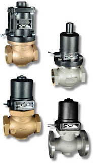
Solenoid Valves - The Operational Basics

industrial solenoid operated valves
Industrial Solenoid Valves
Magnatrol
A solenoid is an electric output device that converts electrical energy input to a linear mechanical force.

At the basic level, a solenoid is an electromagnetic coil and a metallic rod or arm. Electrical current flow though the coil produces a magnetic field, the force of which will move the rod. The movable component of the solenoid is linked to, or part of, the operating mechanism of another device. This allows the switched electrical output of a controller to regulate mechanical movement in another device and cause a change in its operation. A common solenoid application is the operation of valves.

A plunger solenoid contains a movable ferrous rod, sometimes called a core, enclosed in a tube sealed to the valve body and extending through the center of the electromagnetic coil. When the solenoid is energized, the core moves to its equilibrium position in the magnetic field. The core is also a functional part of valve operation. It's repositioning causes a designed changed in the valve operating status (open or close). There are countless variants of solenoid operated valves exhibiting particular operating attributes designed for specific types of applications. In essence, though, they all rely on the electromechanical operating principle outlined here.

A solenoid valve is a combination of two functional units.
  • The solenoid (electromagnet) described above.
  • The valve body containing one or more openings, called ports, for inlet and outlet, and the valve interior operating components.
Flow through an orifice is controlled by the movement of the rod or core. The core is enclosed in a tube sealed to the valve body, providing a leak tight assembly. A controller energizing or de-energizing the coil will cause the valve to change operating state between open and closed, regulating fluid flow. There are almost countless variants of solenoid operated valves, specifically tailored for applications throughout industrial, commercial, and institutional operations.

The document provided below illustrates a portion of the broad array of solenoid valves available for industrial control applications. There are also some good cutaway illustrations showing the internal operating valve parts. Share your valve requirements and challenges with an application specialist. Combining your process application knowledge with their product expertise will produce effective solutions.

Use Electronic Pressure Controllers in Your Research Process Loop to Eliminate Droop, Boost, and Hysteresis

(re-blogged with permission from Brooks Instrument)
Gas pressure control is critical in many applications like life sciences and chemical/petrochemical research where flow is an integral part of the process. Brooks Instrument electronic pressure controllers can be used as they require flow to function. Compared to using a mechanical pressure regulator, electronic pressure controllers eliminate droop, boost and hysteresis, offering stable pressure control.

There are two configurations available for pressure control – upstream and downstream. This terminology is somewhat unique to Brooks Instrument electronic pressure controllers.

Downstream vs. Upstream Pressure Control

downstream vs upstream pressure control diagram
Downstream pressure controllers maintain the pressure downstream of the device itself, increasing flow to increase the pressure and decreasing flow to decrease the pressure. For this reason, this is called direct acting. This configuration is commonly called a standard pressure regulator. A downstream pressure controller acts very similar to a typical mass flow controller because they are both direct acting.

Upstream pressure controllers maintain the pressure upstream of the device itself, increasing flow to reduce the pressure and decreasing flow to increase the pressure. For this reason, this is called reverse acting. This configuration is commonly called a back pressure regulator in the industry.

Selecting and Sizing an Electronic Pressure Controller

The following information is required to select and size a Brooks Instrument electronic pressure controller:
  • Process gas
  • Maximum flow rate being used to maintain pressure -The “sweet spot” for pressure control is between 100 SCCM and 5 SLPM.
  • Calibration pressure (maximum pressure to be controlled)
  • Reference pressure (for upstream controllers the reference pressure is the downstream pressure and for downstream controllers the reference pressure is the upstream pressure)
As long as flow is present in a process you will typically find the need for some type of pressure control. Vessel sizes up to 30 liters commonly use flow rates up to 3 SLPM during their process steps. Brooks Instrument pressure controllers are a perfect fit for these services, offering stable pressure control with no droop, boost or hysteresis, which are commonly experienced when using a mechanical pressure regulator.


Typical Bioreactor Process Using an Upstream Pressure Controller

Handbook on pH and ORP Measurement

pH ORP analyzer transmitter
Dual input pH analyzer and transmitter
Courtesy Yokogawa
Measurement of pH/ORP is a common operation throughout a number of industries. Obtaining true measurements and making correct interpretation of the results can prove challenging without solid working knowledge of the methodology and procedure involved. Certain effects have the ability to cause problems if not taken into consideration.

The book provided below, authored and provided by Yokogawa Electric Corporation, provides a comprehensive understanding of pH/ORP measurement and how to achieve reliable results. Basic information on the principles of measuring pH/ORP, construction of the sensing elements, and their basic use in process applications is provided.

A part of achieving accurate and reliable pH/ORP measurements includes the provision of sufficient electrode strorage conditions and proper maintenance. Prevention of common errors during maintenance and storage, as well as consistent detection of loop failures is important. This book describes how to avoid pitfalls and detect failures.

The book is accompanied with a frequently asked question and answer section as well as an appendix that includes helpful information like a Chemical Compatibility Table and a Liquid-Application-Data-Sheet, which can be used to describe the user’s application.


Miller Energy Introductory Video

Miller Energy is a Manufacturer's Representative and Distributor of Industrial Instrumentation and Process Control Equipment. Since 1958, Miller been committed to exceeding our customers expectations by providing an unparalleled level of customer service and local technical support. Miller Energy maintains two office locations in NJ and PA. The South Plainfield, NJ operation services the areas of Northern NJ, New York, and Fairfield County Connecticut and serves as our corporate headquarters. The Exton PA office serves the areas of Southern NJ, Eastern PA, Delaware and Maryland.


Simplifying Plant Safety Instrumentation

industrial process control safety transmitter and switch
Series One Safety Transmitter and Switch
Courtesy United Electric
Safety implementation typically is accomplished by a group that includes plant instrument engineers and technicians. They are charged with developing simple and reliable solutions that increase safety and reduce risk. Safety related events can involve the question of when to shut a process down. These decisions can hinge on the level of key process variables such as flow, level, temperature and pressure. All must be within their specified range at various locations throughout the process, whether within chemical and petrochemical plants, refineries and power plants, or other processing operations. Critical points of measurement can include anything from process vessels to eye wash stations.

For such point safety applications, a properly designed and implemented digital switch with self-diagnostics can be an important part of the answer. As an element of a multiple technology solution, a digital switch-based approach can help eliminate common-mode failures, significantly improve response time, achieve needed safety integrity levels (SILs), and simplify plant safety instrumentation.

United Electric Controls has authored a white paper entitled "Simplifying Plant Safety Instrumentation" that provides some insight into deployment of safety controls. The entire white paper is included below and will prove to be useful reading. More detailed product and application information is available from product specialists. Combining their product expertise with your process knowledge will produce the best solutions.


"Bubbler Method" Liquid Level Measurement

Brooks Instrument Solid Sense II pressure transmitter for industrial use
An accurate pressure transmitter
is an integral part of  a liquid level
measurement system using the
"Bubbler Method"
Courtesy Brooks Instrument
Measuring liquid level in a tank or vessel can be accomplished in a number of ways, all of which require some arrangement of instrumentation to either infer the liquid level from the measurement of a related physical property, or directly deliver the liquid level visually using a scaled gauge arrangement. One indirect method of level measurement is often referred to as the bubbler method, so named because it employs a purging gas that continually vents from the bottom of a tube extending into a tank of liquid. Through a simple apparatus, the level of a liquid can be inferred by the amount a back pressure exerted upon the gas flowing through the tube.

Probably the greatest advantage of this method of liquid level measurement is that the liquid does not contact the sensing instrumentation. The only portion of the apparatus in contact with the liquid is a tube immersed into the tank. Basically, a purge gas flows through the immersion tube and may bubble out the immersed end of the tube, which is open to allow the contained liquid to exert a hydrostatic pressure on the purge gas. The back pressure on the gas that is exerted by the liquid contained within the tank will vary directly with the depth of the liquid. The back pressure can be correlated to a liquid level. Further calculations, which would include the tank shape, dimensions, and the liquid density can provide an indication of the volume and mass of the liquid. Here is an illustration of the setup, provided courtesy of Brooks Instrument, globally recognized leader in flow and pressure measurement and control. The illustration is from Brooks' January blog article.


diagram of bubbler method tank level measurement apparatus setup
Bubbler Method Tank Level Measurement Apparatus, showing application of some Brooks Instrument devices.
Below are data sheets detailing the components used in the system to control and measure the gas flow, and measure the back pressure on the immersion tube. There are other components needed for a complete system, but they are fairly generic in nature and easily obtainable. Contact a flow and level measurement specialist with your application challenges and work with them to produce effective solutions.


Low Cost Radar Level Transmitter For Industrial Process Applications

non-contact pulse burst radar technology industrial process level transmitter
Magnetrol Model R82 Radar Level Transmitter
With its ability to reliably detect tank liquid surface level under conditions that prove challenging to other methods, radar technology generally provides an operational advantage over other non-contact level measurement options. Historically, the cost of radar level transmitters for industrial process control applications has hindered their success as a unit of choice for some installations. Magnetrol has changed that imbalance with their recent introduction of a lower cost radar level transmitter for tough applications.

The Model R82 provides radar performance at a price point comparable to competitive ultrasonic units, but maintains the performance advantage inherent in a radar based device. The unit utilizes pulse burst radar technology at 26 GHz, employing advanced signal processing to filter out false echos produced by a range of in-tank conditions that can produce false readings from ultrasonic units.

The short video below provides a closer look at the R82 and its performance advantages. Technical data sheets and any application assistance you may need is available from product specialists. Share your level measurement and control challenges with them and work toward the best solution.

Yokogawa Users Conference and Exhibition is Coming

Yokogawa is presenting its 2016 Users Conference and Exhibition in Orlando, Florida. The event runs from October 3 through October 6 and will be held at the Renaissance Orlando at SeaWorld hotel. Included in the conference agenda are informative technical sessions, training workshops, panel discussions, hands-on demonstrations, essential application sessions, and daily keynote speakers. The opportunities for networking and learning are truly unique and rewarding for those involved in process automation and control.

There is currently a call for presentations, seeking out those who wish to share their applications and challenges. Learn more about the conference and register at the event website.


Yokogawa Publishes New Collection of Case Studies in Process Automation and Control

Yokogawa, an internationally recognized process automation and control provider, strives for customer satisfaction through operational excellence, bringing long-term success to its customers. Now available are collections of actual cases in which Yokogawa helped leading companies in a variety of industries address specific challenges and achieve their goals. The new e-books were redesigned and subdivided into six sectors including LNG, Oil & Gas, Chemical, Pharmaceutical, and Renewable Energy.

Browse the e-books online for insight into the breadth and depth of Yokogawa's capabilities and their commitment to their customer's success. Depending on your screen size, you may need to scroll down the page to see the e-books at the link. At e-books, you can browse using the online reader, or download them as a PDF file.

Share you process control challenges with a Yokogawa representative and expect the best solutions.

Save Time And Get The Right Product With Yokogawa Automated Selection Tool

Yokogawa Corporation of America, an industry recognized source for innovative process measurement and control products, has made available an easy to use product selection tool for those navigating through the company's extensive product offering. The Product Finder is a great time saver that enables a user to quickly locate product and technical information on Yokogawa process instrumentation products meeting the user's selected criteria.

Let's step through a quick example. You will see how this quick and easy to use tool saves time by navigating quickly to the website pages detailing products meeting your requirements.

The Product Finder is accessible through a number of links throughout Yokogawa's network of representatives. Clicking the link lands you on the start page of the Product Finder. For this example, I am going to search for a flow meter with the following characteristics:


  • Mass flow measurement 
  • Non-conductive liquid
  • Accuracy of 1%
  • Flow measurement device must have an integral transmitter
  • Tri-clamp connections


Above, I declared my location as United States. The next step, shown below, is to select "Flow" as the measurement parameter. You will see in the drop down menu that there are many measurement elements that can be selected, with Yokogawa products for each.


My selection of "Flow" from the drop down menu returns all of the company's flow measurement devices, of which there are many (this cropped screenshot, shown below, only shows four, but there were many more) . This is where the selector really helps you. Instead of examining several or many different models, the user can focus the search by adding more product characteristics. You can see the list of prompting questions on the left side of the page. Providing additional characteristics by answering the prompting questions will narrow the search results to the show only the products meeting all the criteria specified by the user.


The next image (below) shows all of my sample product attributes entered on the left column. Note that there is now only a single product that matches all of my sample criteria. The whole process took less than two minutes. By clicking on the "View More Details" button below the product image, I gain access to all of the available technical, support, and product data for my selected flow measurement device.


The process instrumentation specialists at Miller Energy are available to provide additional help in meeting your measurement challenges. Combine their product knowledge and expertise with your process know-how for the best solutions.

Vortex Flowmeter Delivers High Performance in Harsh Process Conditions

Yokogawa vortex flowmeter
digitalYEWFLO Vortex Flowmeter
Courtesy Yokogawa
In the process measurement and control field, vortex flowmeters are noted for their ruggedness, versatility, comparatively high accuracy, and absence of moving parts. They are compatible with numerous applications requiring measurement of flow in gases, liquids, and steam. The Yokogawa digitalYEWFLO vortex flowmeter is an accurate and stable device, even in harsh process conditions, and has a highly reliable and robust design that can deliver improvements in plant efficiency and reduced operating costs. It is available in several versions, one of which is multivariable, providing a calculated mass flow rate output.

Operating Principle

When a shedder bar is placed in a flow, Karman vortices are generated on the downstream side of the bar. The Karman vortices are detected by two piezoelectric elements installed in the upper part of the shedder bar. The vortex frequency is proportional to the flow velocity in a specific range of Reynolds numbers. Therefore, flow velocity or flow rate can be determined by measuring vortex frequency.

Noise Reduction

Noise caused by strong piping vibration may affect the accuracy of vortex frequency detection. The two piezoelectric elements in the digital YEWFLO are installed in a configuration that is polarized, so they are not affected by vibration in the flow or vertical directions. The noise of vortex (lift)- direction vibration is reduced by adjusting the outputs of the piezoelectric elements. Combining these features with the Spectral Signal Processing (SSP) function provides optimum and stable measurement.

Share your process measurement challenges with a product application specialist. The sharing of ideas and information will produce the best outcome.


Develop a Thoughtful and Comprehensive Alarm Plan for Process Control Operations

Petrochemical piping at industrial processing plant with process control
Petrochemical plants are one of many industrial process
control operations to benefit from comprehensive alarm plans
Industrial process control operators and designers have the capability to measure many aspects of machine operation and process performance. Determining the elements to measure, method of measurement, and how to handle and process the derived information can be challenging, but can also impact the security, performance, and safety of an operation. A plan for monitoring, reporting, and responding to abnormal process conditions, if properly developed and executed, can yield real benefits to a process operator. A protocol that is not well conceived may produce a negative operational impact by creating events that unnecessarily draw resources away from productive endeavor. That protocol, or plan, is often referred to as an alarm plan.

There are numerous forces that can influence the development and implementation of an alarm plan. Each operation must incorporate its own set of external regulatory requirements, internal procedures and policies into a complete alarm protocol. Distilling that macro description down to a workable set of procedures and response tasks is where the real work begins. There is, however, a basic framework that can help organize your thinking and focus on what is most important.

  • What parameters define the process or operation?
    Produce a schedule of every non-human element that is required to make the process function. This will require drilling down through every machine and material that is part of the operation. Expect the schedule to be extensive, even huge. If it is not, consider that your analysis may not be reaching deep enough. The goal here is to create an overview of what makes the process work and provide a tool for systematically studying the process elements and gleaning possible commonalities or relationships among them. Consider disregarding things that cannot be measured, since that prevents the derivation of data for evaluation. Review the completed schedule and decide which parameters shall be measured and evaluated for proper performance.
  • What level of measurement is needed for each monitored parameter?
    An assessment of the needed accuracy, frequency, and resolution for parameter measurement will help define the requirements for instrumentation or other devices used to monitor a particular item. The goal is to make sure the monitoring device is capable of detecting and delivering information of sufficient quality to make decisions.
  • Define the limits of acceptability for each monitored parameter.
    Until the endpoint of the process or operation, each step is likely dependent in some way on previous steps. The output of each step becomes the input of the next. While this, in many cases, may be an oversimplification, it is important to consider the relationships between the tasks and operations that comprise the process. Monitored parameters should relate to the successful completion of a process step, though not necessarily be a direct indicator of success. The maintenance of the parameter within certain bounds may be used as an indicator that a component of successful completion was properly attained. Defining limits of acceptability may involve an element of subjectivity and will likely be customized to accommodate the process. Each organization shall evaluate their operation and determine limits based upon intimate process knowledge and experience.
  • Define abnormal operation for each monitored parameter.
    Abnormal operation may not necessarily be any value not within what is considered acceptable. Consider abnormal to be the range of values that would be cause for notification of the operator, or even automated or human intervention. Note that the definition of unacceptable or abnormal operation might appropriately include filters or defined relationships with other parameters. An example of a simple filter is a time delay. If the measured variable exceeds the specified limit for 2 seconds, it make not be significant. If the threshold is exceeded for 2 minutes, it may be cause to take action. As with the limits of acceptability, developing the definition of abnormal operation for each parameter will be customized for each process.
  • Provide a defined response for every alarm occurrence.
    If it is important to monitor something, then it is likely important to do something when things get out of hand. Human executed alarm response should be concise and uncomplicated, to reduce the probability of error. Automated response should be designed in a manner that provides for functional testing on a regular basis. The scope of the response will be specific for each process, with the level of response depending upon factors determined by the process operators. Response can be as simple as annunciating the condition at a monitoring station, or as dire as shutting down part or all of the process operation.
  • Review every alarm event.
    Each alarm event should be logged and reviewed. Consider whether the event detection and response was adequate and beneficial. If the results were less than expected or desired, assess whether changes can be made to provide improved results in the future. The alarm plan is unlikely to be perfect in its first incarnation. Be prepared to reevaluate and make changes to improve performance.
The exercise of developing a comprehensive alarm plan will help to build understanding of process operation for all involved parties. This article is but a brief synopsis of the subject, intended to get the reader on the path of developing a useful alarm plan. Your alarm plan should an extension of process operation decision making, and have a goal of enhancing safety and reducing loss. Contact the process control and combustion specialists at Miller Energy for additional input.

LOGIIC - Cybersecurity Confederation for Industry Video

oil refinery with tanker ship
Oil Refinery
In response to the challenges presented by malicious or mischievous cyber operatives, a number of organizations joined together to collaborate in the design, testing, and implementation of tools and techniques to protect critical industrial systems on a global scale. LOGIIC (Linking Oil and Gas Industry to Improve Cybersecurity), as its name implies, focuses on the oil and gas industry. We should all know, however, that a substantial portion of the automation and process control devices we regularly utilize throughout many industries today were originally developed in the oil and gas industry, where the operational scale and risk level are sufficiently high to justify the costs of developing new technology, methods, and equipment.

LOGIIC participants include the Automation Federation, which brings the resources of world class device and software manufacturers to bear on cybersecurity issues of the day. The Cyber Security Division of the Science & Technology Directorate in the US Department of Homeland Security is also involved. Currently, five major oil companies are members.

Since its inception, LOGIIC has successfully completed eight major projects, with plans for many more. Upon completion of selected projects, LOGIIC delivers public reports to help elevate best practices across the entire industry. Both the member companies and the government are putting funds towards these projects which benefits not only the private sector, but also the public interest. Companies are applying the results within their organizations, because it helps bridge the gap between information technology and the industrial-environment sides of the organization.

LOGIIC is an organization that conducts activities and disseminates information that can be useful throughout your own organization and that of your customers and suppliers in the industrial process control field. Below is a video highlighting the organization and its work.