Showing posts with label level measurement. Show all posts

Magnetic Level Indicators and Controls for Industrial Process Applications

Magnetic Level Indicators and Controls

Fluid process control operations frequently involve the storage of liquids in a vessel or tank. The continuous and accurate indication of the liquid level within the tank is an important data point for process control decision making and safety. Several tank level measurement methods and instrument types are available, each with its own set of characteristics that may be advantageous for a specific installation. 

A tank liquid level indicator's selection criteria often include: 

  • Does the process require direct or indirect measurement of level?
  • What level measurement accuracy and reliability is needed?
  • What is the tank shape, regular or irregular?
  • Are there concerns with media compatibility with measurement device materials of construction?
  • How often will maintenance or calibration be needed?
  • Is the instrument capable of operating at the process temperature and pressure for the application?
  • Does the application require local display and visibility or remote?
  • Are control signals from the level indication required? What type and transmission protocol?
  • What kind of redundancy and safety devices, such as additional switches, are needed?

Magnetically coupled liquid level indicators, or MLIs, are widely used in the process industry. They are accurate, consistent, and reliably indicate liquid level. These units are completely sealed and do not require any maintenance. MLIs also eliminate the vapor or liquid emission issues that plague sight and gauge glasses. 

Most Compelling Reasons for Using MLI's:

  • Level measurement is continuous. 
  • Operable without the use of electricity. 
  • Regardless of tank shape or profile, they provide a direct visual tank fluid level indication. 
  • They are available in wide operating temperature and pressure ranges. 
  • MLI construction is resistant to breakage.
  • A variety of materials are available to accommodate corrosive media. 
  • Externally mounted measuring indicators, switches, and transmitters do not come into contact with the process media. 
  • MLI's provide a continual operation that requires little maintenance. 
  • The level indication is viewable from a greater distance than glass sight gauges. 
  • With a single instrument, it is possible to measure large fluid level ranges.

Magnetic level indicators have a strong presence in tank liquid level measurement and should be considered a candidate for meeting those application requirements. There are numerous options for customizing the level indicator for each application.  Work with your local Sales Engineer,  a specialist in level measurement, about your application challenges and positive outcomes. 

For more information, contact your local Miller Energy, Inc. regional office:

South Plainfield, NJ Office
Serving Northern NJ, New York, and Fairfield County Connecticut
South Clinton Ave.
South Plainfield, NJ 07080
Phone: 908-755-6700
Toll Free: 800-631-5454
Fax: 908-755-0312

Exton, PA Office
Serving Southern NJ, Eastern PA, Delaware and Central and Eastern Maryland
505 Gordon Drive
Exton, PA 19341
Phone: 610-363-6200
Toll Free: 888-631-5454
Fax: 610-524-7254

Cleveland, OH Office
Serving Ohio
555 Golden Oak Parkway
Cleveland, OH 44146
Phone: 440-735-0100
Fax: 440-735-0123

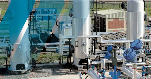
Liquid Interface Level Measurement Using Guided Wave Radar, Magnetic Level Gauges, Float & Displacer, Thermal Dispersion, and RF Capacitance

Liquid Interface Level Measurement

The need for interface measurement arises whenever immiscible liquids - those incapable of mixing - reside within the same vessel. The lighter material rises to the top and the heavier material settles at the bottom. In oil production, for example, water or steam is used to extract oil from a well. Well fluids then route to production separators where they settle into their primary constituent parts as a water-hydrocarbon interface. Water may also be used as a transport medium or a cleaning agent and forms an interface with an allied material which is later extracted.

Knowing the position of a process interface is necessary for maintaining product quality and operations efficiency. The interface is measured and controlled by precision level switches and transmitters. Though at least 20 different types of liquid level measurement devices are in service today, only a very few are suitable for accurate and reliable interface measurement. Grouped by their operating technologies, these include Buoyancy (Floats and Displacers), RF Capacitance, Thermal Dispersion, Radar, and Redundant Technologies (those combining two measurement technologies in one instrument).

Interface Level Measurement
The five leading interface measurement technologies in use today are Guided Wave Radar, Magnetic Level Gauges, Float & Displacer, Thermal Dispersion, and RF Capacitance. These five leading interface measurement technologies in use today are discussed in the technical bulletin titled "Liquid Interface Level Measurement" and produced by Magnetrol International.


For more information on any industrial level control application, contact Miller Energy. Call them at 800-631-5454 or visit their website at https://millerenergy.com.

Radiometric, Non-contact Level Measurement for Liquids or Solids

Radiometric level detection
(RONAN)
Radiometric level measurement, using a very low gamma level source, is designed to deliver outstanding performance in a wide range of difficult applications and process conditions for both liquids and bulk solids which include the most dangerous materials such as caustic, toxic, corrosive, explosive, and carcinogenic irrespective of their viscosity and temperature.

These level gauges meet “As-Low-As-Reasonably-Achievable” (ALARA) guidelines. Source activity is customized depending on vessel and process parameters such as diameter, wall thickness, material, and measurement span to ensure optimum sensitivity, economy and safety while keeping the source activity to a minimum.

Non-contact level
Sources and Detector Mounted
External to Vessel
An exclusive “Radiation Low Level” (RLL) source holder uses up to 100 times less gamma energy than comparable gauges, and is the only source holder recognized by the NRC to be so safe that it does not require the stringent documentation, training or handling procedures of other systems.

Operation

Radiometric level measurement provides a safe and efficient, non-contact method to measure liquids or solids in harsh process environments. Each system consists of a gamma source, detector and microprocessor.

  • The gamma source, typically mounted external to the vessel emits energy through the vessel walls collimated in a direction towards the detector mounted on the opposite side of the vessel. The gamma energy reaches the detector when the vessel is empty. As the process level rises in the vessel, the gamma energy reaching the detector will decrease in an inversely proportional relationship to the level. 
  • The detector measures the level of energy and sends a proportional signal to the microprocessor. 
  • The microprocessor linearizes, filters, and correlates this signal to a level measurement. 

The entire system is mounted external to the vessel and can be easily installed and maintained while the process is running ... without expensive down time, vessel modifications or chance of accidental release.

Applications
Low Level Source and Detector
Mounted External to Vessel
  • Radiometric level detection
  • Low Level Source and Detector
  • Mounted External to Vessel
  • Solids or Liquid Measurement 
  • Measurement Not Affected by: 
  • Internal Obstructions. i.e. Agitators Extreme Process Temperatures 
  • Caustic Processes 
  • Violent Product Flow 
  • Sterile Process 
  • Changing Process 
  • Variable Product Flow 
  • Automatic Compensation for Vapor Density Changes 
  • Automatic Compensation for Foam or Gasses 
  • Automatic Compensation for Process Build-Up 
  • Detectors Contoured to the Shape of Vessels 
  • Upgrade Utilizing Existing Sources
Features and Benefits 
  • Accurately Measures the Most Complex Processes 
  • Solid Crystal or Flexible Scintillating Fill- Fluid 
  • Excellent Measurement Reliability due to Proprietary Filtering Technology 
  • Level Detection of Multiple Interfaces 
  • Low Maintenance / No Component Wear 
  • Auto-Calibration

For more information in Eastern Pennsylvania, New Jersey, Metro New York or Delaware contact:
Miller Energy by visiting https://millerenergy.com or by calling 908-755-6700 in New Jersey, or 610-363-6200 in Pennsylvania.

Innovative Non-Contact Radar Liquid Level Transmitter

non-contact radar level transmitter for industrail process control
Pulsar R86 non-contact radar level transmitter.
Image courtesy Magnetrol
Level measurement of liquids and solids in containers, silos, tanks and other vessels is an essential part of many processing operations. Accurate and reliable measurement of solids or liquid level contributes to operational success, as well as enhancing safety, both of which contribute to the bottom line and successful operation.

Magnetrol, globally recognized innovator in flow and level measurement, incorporates years of experience into their latest version of non-contact radar level measuring instruments. The incremental improvements contribute to easier, more flexible installation and better performance.

The R86 is a 26 GHz level transmitter applicable across a wide range of requirements in many industries. Benefits of the 26 GHz radar signal, with its smaller wavelength, are a smaller antenna and improved 1mm resolution. The narrower beam from the antenna makes positioning the transmitter less restrictive, with easier accommodation for vessel fixtures or geometry. Advanced on board diagnostics supplement the improved performance and deliver the information needed to maintain proper operation and process visualization. A broad range of antennas and mountings are available for the R86, accommodating various tank sizes, fittings, and temperatures

More information on the Pulsar R86 is provided in the brochure included below. Share your level measurement challenges and requirements with a process measurement specialist. Employ the leverage of their product application expertise to your own process knowledge and experience to develop an effective solution.


New Pulsar R86 Non-contact Radar Level Transmitter From Magnetrol

non-contact radar level transmitter
Magnetrol's new non-contact radar level transmitter,,
Pulsar R86
Courtesy Magnetrol
Level measurement is a part of countless industrial processes and installations. Accurate measurement of contained solids or liquid enhances safety and operational efficiency, both of which contribute to the bottom line.

Magnetrol, globally recognized innovator in flow and level measurement, recently released its latest version of non-contact radar level measuring instruments. The Pulsar R86 transmitter operates in the 26GHz range, delivering a smaller wavelength with improved resolution, smaller antenna, and a narrower beam. Other unique innovations have been incorporated into the instrument to simplify installation and application.

The R86 is suitable for a broad range of applications across almost every industry. On board diagnostics are incrementally advanced to provide best performance and deliver the information needed to maintain proper operation.

The latest information on the Pulsar R86 is included below. Reach out to process measurement specialists and share your measurement challenges and requirements. Combining your own process knowledge and experience with their product application expertise will result in an effective solution.


E-Book on Fired Heaters and Combustion Efficiency

industrial equipment in high power boiler room
Modern high power boiler room
Yokogawa, globally recognized leader in a number of process control fields, has authored an e-book which provides useful insight into how operators of combustion based equipment and systems can improve efficiency and enhance safety by employing modern technology.

[All quoted passages in this article are from the Yokogawa e-book]

The Yokogawa e-book Combustion & Fired Heater Optimization offers “an analytical approach to improving safe & efficient operations” related to the use of combustion & fired heaters in the process industries. Through presenting an overview of combustion sources, such as furnaces and fired heaters, the book states that while “fired heaters pose a series of problems from safety risks to poor energy efficiency,” those problems “represent an opportunity for improved safety, control, energy efficiency and environmental compliance.” Fired heaters “account for 37% of the U.S. manufacturing energy end use.” Tunable Diode Laser Spectrometer (TDLS) technology helps mitigate safety concerns by “measuring average gas concentrations across the high temperature radiant sections.”

The book states that the four main concerns applicable to fired heaters are asset sustainability, inefficient operations, the operator skillset, and safety and compliance. Outdated diagnostics and controls have placed unnecessary stress on operator response, making sustainability of fired heaters difficult. The emissions of fired heaters are generally higher than designed, and can be coupled with control schemes for firing rates little changed over the past 40 years. Operators, generally, lack a clear understanding of design, and even engineering principles of heat transfer are not typically included in education related to fired heaters. Confounding the situation further, “many natural draft heaters do not meet this [safety regulation] guideline with existing instrumentation and control systems.” These complications combine to form a noticeable problem Yokogawa’s technology hopes to address. The company notes how the fired heater relies on natural draft instead of forced air, meaning the heaters “typically lack the degree of automation applied to other process units in the plant.” Offering a full detail of both the control state of most fired heaters and their systems defines the process situation currently considered common in the field, while emphasizing high excess air as providing a “false sense of safety.”

The proposed TDLS system allows for the measurement of “both the upper and lower conditions in a fired heater” by “simultaneously controlling the fuel and air supply based on fast sample intervals.” Safer burner monitoring and heater efficiency results from the TDLS measurements of CO, CH4, and O2. The optimization of air flow control reduces “O2 concentration … from 6% to 2%” and increases the furnace’s thermal efficiency. Combustion control is achieved by managing fuel flow and the arch draft. The TDLS integrated system works in tandem with already established logic solver systems in the plant. The TDLS technology works as a non-contacting measurement with “full diagnostic capability” and offers “distinct advantages over single point in situ analyzers” via reduction of false readings. Specific gas measurements, fast response time, optical measurement technology, and “high and variable light obstruction” are featured components of the TDLS system highlighted to show the technology’s durability and flexibility. The longevity and reliability of the system is showcased by how the TDLS combustion management system has been operational in a major refinery since 2010. The percentage of excess O2 in sample fired heaters has decreased by 1% to 1.5%. Measurements by the TDLS system have been verified by other gas analyzers. The furnace conditions in the plant are more efficiently monitored and controlled. As a result, the furnace in the functional environment is “now near its optimum operating point, using minimum excess air.”
Yokogawa presents a process-related problem, then details the key points of the problem while unpacking the causes. The e-book introduces Yokogawa’s technology, explains the mechanics, and demonstrates how TDLS acts as a solution to the problem, supported by a tangible example. The book offers great insight for both the operational principles of fired heaters and a new technology designed to maximize efficiency in the control process.


The e-book is included below. More detail is available from product applicationspecialists, with whom you should share your combustion and fired heater related challenges. Combining your own facilities and process knowledge and experience with their product application expertise will lead to effective solutions.


Level Measurement Using Isolating Air Flow

illustrated diagram of instruments used for bubbler liquid level measurement
Bubbler method of liquid level
measurement is simple and reliable
Courtesy Yokogawa
Remotely utilized measurements of tank liquid level are common throughout the fluid processing industries. Various means of inferential or direct measurement are available, each with its own set of performance, maintenance, and cost attributes that may make it the preferred choice for a particular application.

Inferring liquid level using a hydrostatic pressure measurement is a simple, easy to implement strategy for delivering a continuous level signal to the process operating and control system. There can be situations where mounting the measuring gear near the bottom of a tank or other vessel may be impractical or undesirable. A pressure transmitter mounted low on a tank may expose it to damage from plant traffic or other physical hazards. It is also possible that the tank may not have a suitable fitting located low enough to provide the needed measuring range. Having a potential leakage point at a fitting low on the tank may also be undesirable. Another, and certainly not final, scenario would be an application involving a corrosive liquid which must not come in contact with the pressure sensor.

The bubbler method of liquid level measurement employs an arrangement that overcomes all of the previously mentioned impediments. It can utilize connections at the top of the tank, above the liquid level. The way in which the method works will keep the pressure sensor out of contact with the process liquid, providing isolation from potential corrosive effects.

The apparatus for level measurement using the bubbler method employs a simple dip tube that extends from the pressure sensor or transmitter to nearly the bottom of the tank or vessel. A small amount of purge air or gas continually flows through the dip tube and will bubble out the bottom of the tube. This dip tube arrangement essentially transfers the hydrostatic pressure at the bottom opening of the tube to the pressure transmitter, while the purge gas keeps the liquid from advancing up into the pipe. The bubbler can be used on atmospheric or pressurized tanks with a properly configured pressure or differential pressure transmitter.

Probably the most significant application point of the bubbler method that will distinguish its use from many other level measurement methods is the importance of maintaining air or gas flow in the dip tube. The flow provides isolation of the sensor, but the flow must also be set to a level that will not impact the pressure measurement in the tube itself. If the flow is excessive, backpressure in the tube can be offset from the level imparted by the tank contents, with the result being an incorrect measurement.

Below is an application note from Yokogawa, showing how their pressure transmitters and rotameters can be used to create the setup. Share your process measurement challenges and requirements with instrumentation experts, combining your own process knowledge with their product application expertise to produce effective solutions.