Showing posts with label industrial valve. Show all posts

Miller Energy Expands Product Offering

general purpose solenoid valves for industrial use
Miller Energy is now a distributor of Asco solenoid
valves for a wide range of general and special applications
Miller Energy, through its acquisition of a New Jersey based distributor, has greatly expanded the company's offering of solenoid valves, pneumatic system components, and fluid handling and control components.

A solenoid is an electrical device, converting electrical energy input to a linear mechanical force. Solenoids are used to provide rapid two state mechanical movement of other devices. In process control applications, those devices are often fluid control valves.

At the basic level, a solenoid is an electromagnetic coil and a metallic rod or arm. Electrical current flow in the coil creates a magnetic field which will position the rod in one of two locations, depending upon whether the coil is energized. The movable component of the solenoid is linked to, or part of, the operating mechanism of another device. This allows the switched electrical output of a controller to regulate mechanical movement in another device and cause a change in its operation. A common solenoid application is the operation of small valves.

A plunger solenoid contains a movable ferrous rod, sometimes called a core, enclosed in a tube sealed to the valve body and extending through the center of the electromagnetic coil. When the solenoid is energized, the core moves to its equilibrium position in the magnetic field. The core is also a functional part of valve operation. It's repositioning causes a designed changed in the valve operating status (open or close). There are countless variants of solenoid operated valves exhibiting particular operating attributes designed for specific types of applications. In essence, though, they all rely on the electromechanical operating principle outlined here.

A solenoid valve is a combination of two functional units.
  • The solenoid (electromagnet) described above.
  • The valve body containing one or more openings, called ports, for inlet and outlet, and the valve interior operating components.
Flow through an orifice is controlled by the movement of the rod or core. The core is enclosed in a tube sealed to the valve body, providing a leak tight assembly. A controller energizing or de-energizing the coil will cause the valve to change operating state between open and closed, regulating fluid flow. There are almost countless variants of solenoid operated valves, specifically tailored for applications throughout industrial, commercial, and institutional operations.

The document provided below illustrates a portion of the broad array of solenoid valves available for industrial control applications. Share your fluid control requirements and challenges with an application specialist. Leverage your process knowledge and experience with their product application expertise to produce effective solutions.


Industrial Control Valves

cutaway view of industrial control valve plug valve
Cutaway view of industrial control valve
Courtesy Cashco
Control valves are at the heart of almost every fluid based industrial control process. Understanding their basic operation and function is essential for the process engineer, operator, or other stakeholder. A previous blog provided a good information source for those wishing to learn about control valves or review and hone their technical knowledge. The applications for which control valves are used seem uncountable in their variety, but common operating traits of control valves enable their use in every one.

Cashco, globally recognized manufacturer of industrial control products including control valves, regulators, controllers, pressure/vacuum relief vents, and flame and detonation arrestors, will be exhibiting at Interphex in Booth 3464 on March 21 through March 23 at the Jacob Javits Center in New York City. Knowledgeable personnel will be on hand to discuss your industrial control applications and challenges. If your plans include attendance at Interphex this year, take advantage of the opportunity to speak face to face with representatives of an industry leader.


Solenoid Valves - The Operational Basics

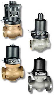
industrial solenoid operated valves
Industrial Solenoid Valves
Magnatrol
A solenoid is an electric output device that converts electrical energy input to a linear mechanical force.

At the basic level, a solenoid is an electromagnetic coil and a metallic rod or arm. Electrical current flow though the coil produces a magnetic field, the force of which will move the rod. The movable component of the solenoid is linked to, or part of, the operating mechanism of another device. This allows the switched electrical output of a controller to regulate mechanical movement in another device and cause a change in its operation. A common solenoid application is the operation of valves.

A plunger solenoid contains a movable ferrous rod, sometimes called a core, enclosed in a tube sealed to the valve body and extending through the center of the electromagnetic coil. When the solenoid is energized, the core moves to its equilibrium position in the magnetic field. The core is also a functional part of valve operation. It's repositioning causes a designed changed in the valve operating status (open or close). There are countless variants of solenoid operated valves exhibiting particular operating attributes designed for specific types of applications. In essence, though, they all rely on the electromechanical operating principle outlined here.

A solenoid valve is a combination of two functional units.
  • The solenoid (electromagnet) described above.
  • The valve body containing one or more openings, called ports, for inlet and outlet, and the valve interior operating components.
Flow through an orifice is controlled by the movement of the rod or core. The core is enclosed in a tube sealed to the valve body, providing a leak tight assembly. A controller energizing or de-energizing the coil will cause the valve to change operating state between open and closed, regulating fluid flow. There are almost countless variants of solenoid operated valves, specifically tailored for applications throughout industrial, commercial, and institutional operations.

The document provided below illustrates a portion of the broad array of solenoid valves available for industrial control applications. There are also some good cutaway illustrations showing the internal operating valve parts. Share your valve requirements and challenges with an application specialist. Combining your process application knowledge with their product expertise will produce effective solutions.

Cavitation - Scourge of Industrial Process Control Valves Everywhere

Cavitation produces vapor bubbles in liquids
Cavitation produces bubbles in flowing process liquids
Consider a generic industrial fluid process control operation. There are pumps, valves, and other components installed in the process lines that, due to their interior shape or their function, cause changes in the fluid motion. Let's look specifically at control valves and how their throttling operation can create conditions able to greatly impact the valve itself, as well as the overall process.

Fluid traversing a control valve can undergo an increase in velocity when passing the constriction presented by the valve trim. Exiting the trim, fluid then enters the widening area of the valve body immediately downstream with a decrease in velocity. This change in velocity corresponds to a change in the kinetic energy of the fluid molecules. In order that energy be conserved in a moving fluid stream, any increase in kinetic energy due to increased velocity will be accompanied by a complementary decrease in potential energy, usually in the form of fluid pressure. This means the fluid pressure will fall at the point of maximum constriction in the valve (the vena contracta, at the point where the trim throttles the flow) and rise again (or recover) downstream of the trim.

This is where cavitation begins.

If the fluid being throttled is a liquid, and the pressure at the vena contracta is less than the vapor pressure of the liquid at the flowing temperature, portions of the liquid will spontaneously vaporize. This is the phenomenon of flashing. If, subsequently, the pressure of the fluid recovers to a level greater than the vapor pressure of the liquid, any flashed vapor will rapidly condense, returning to liquid. This collapse of entrained vapor is called cavitation.

Flashing, the generation of vapor bubbles within the liquid, will precede and set the stage for cavitation. When the flashed vapor bubbles condense to liquid they often do so asymmetrically, with one side of the bubble collapsing before the rest of the bubble. This has the effect of translating the kinetic energy of the bubble’s collapse into a high-speed “jet” of liquid in the direction of the asymmetrical collapse. These liquid “microjets” have been experimentally measured at speeds up to 100 meters per second (over 320 feet per second). What is more, the pressure applied to the surface of control valve components in the path of these microjets can be intense. An individual microjet can impact the valve interior surfaces in a very focused manner, delivering a theoretical pressure pulse of up to 1500 newtons per square millimeter (1.5 giga-pascals, or about 220000 PSI) in water. In an operating fluid system, this process can be continuous, and is known to be a significant cause of erosive wear on metallic surfaces in process piping, valves, pumps and instruments. As the rapid change in pressure takes place, the bubbles (voids in the liquid) collapse (implode), and the surrounding metal surfaces are repeatedly stressed by these implosions and their subsequent shock waves.

Consequences for control valves, as well as for the entire control process, vary and are often destructive. They may include:
  • Loud noise
  • Strong vibrations in the affected sections of the fluid system
  • Choked flow caused by vapor formation
  • Change of fluid properties
  • Erosion of valve components
  • Premature destruction or failure of the control valve 
  • Plant shutdown
The video provides a visual demonstration, through clear piping, of what happens inside the piping system when a valve is operated in a manner that causes substantial cavitation.

The solution lies in minimizing the potential for cavitation to occur through proper valve selection and sizing, along with coordinating operating characteristics of pressure drop inducing components with the total system performance. One valve manufacturer's recommendations are summed up in four basic approaches.
  • Avoidance of cavitation through proper valve selection. Use a valve with a rated liquid pressure recovery factor greater than that required for the application. Some applications may be suitable for the use of an orifice plate downstream of the valve.
  • Cavitation Tolerant Components capable of withstanding limited amounts of cavitation without excessive wear. Increased flow noise is likely to accompany this route.
  • Prevention of cavitation through the use of valve trim design that reduces pressure in several steps, avoiding excessive flashing. These valves can be expensive, but their effectiveness makes them an alternative worth considering.
  • Containment of the harmful effects of limited to moderate cavitation through trim designs that eliminate contact of the fluid with metal surfaces which are more susceptible to damage.
Share your requirements and application challenges with a valve specialist and gain insight through their recommendations. Combining your process knowledge with their product application expertise will yield a great solution.


Know Your Control Valve Basics?

Industrial Control Valve Cutaway View
Courtesy Cashco
Understanding basic operation and function of control valves, an integral part of many industrial process control loops, is essential for the process engineer, operator, or other stakeholder. This presentation outlines control valve operation, major components, and terminology used to describe valve parts, functions, and principles of operation. A useful reference for stakeholders in need of a refresher course in order to understand what the engineers are saying, it also provides detailed illustrations, charts, and description that will prove valuable to the more technical minded.


What you will find:


  • Terminology: A glossary of terms commonly used in the control valve world.
  • Control Valve Basic Designs: Control valve classifications, cutaway illustrations showing the operating structure of different valve types, comparisons of varying valve designs.
  • Characterization and Trim Design: Flow characteristic curves and comparisons for different valve types, showing how flow responds to valve position change.
  • Control Valve Technical Considerations: FTC vs FTO, illustrations showing valve operation.
  • Force-Balance Principle: Illustration and formula explanations of this basic operating principle.
  • Actuator Basic Designs: Illustrations showing the differing arrangements for actuator operation.
  • Control Valve Unit Action: Illustrations, diagrams, and explanations of a range of valve operating conditions, including loss of electrical power and loss of instrument air supply.
  • Actuator Benchset Range: Shows practical relationship between instrument air pressure and valve ability to properly operate at various pressure conditions.
  • Valve Positioner Basics: Definition of valve positioning, reasons to use a positioner, schematic illustrations of control loops.
  • Control Loop Action: Charts and provides examples of 16 combinations of Process, Controller, Positioner, and Control Valve combinations.
  • Control Valve Packing Designs: Describes and defines packing, common problems, current state of the art. Cutaway illustrations of various packing arrangements.
  • Seat Leakage: Classifications, comparisons of different materials.


There is something of value in the document for everyone, and you will undoubtedly pick up something useful. Thanks go out to the engineers at Cashco for putting this together. You can discuss any aspect of your control valve applications with a product specialist. Your contact is always welcome.


Miller Energy - Industrial Instrumentation and Process Control Solutions

Miller Energy is a Manufacturer's Representative and Distributor of industrial instrumentation and process control equipment.  Miller is committed to exceeding customers expectations by providing an unparalleled level of customer service and local technical support.

Miller offers the most comprehensive line of measurement, control, and communication solutions in industry today. The products provided by Miller solve challenging applications in the industrial gas, power, refining, chemical / petro-chemical, food & beverage, water/wastewater, and pharmaceutical markets.

Valve Selection: A Look at Ball Valves

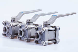
industrial ball valves
Industrial Application Ball Valves
In the realm of industrial process control valves, your selections for most applications are vast. Every application will likely have one or more elements become critical and deciding factors for valve selection. That element might be complex and highly technical, being intimately related to physical or dynamic properties few understand. Conversely, the selection may hinge upon something as obvious as what will fit in the space that is provided. Whatever the case, some efficiency can be brought to bear in your selection process by initially deciding which type of valve would best suit the application. This allows you to focus on a much smaller universe of product candidates for your project.

Like most valves, ball valves are characterized by their closure mechanism.  Generally, a ball valve has a spherically shaped fabrication (ball) that is inserted in the fluid flow path. The ball has an opening through its center, often circular in cross section and matching the diameter and shape of the connected pipe. The ball is contained within the body of the valve and rotated around its central axis by torque applied to the stem. The stem, which extends through a seal to the exterior of the valve body, can be manually or automatically controlled via several methods.

During valve operation, the ball is rotated through a ninety degree arc from a fully closed to fully open position. When fully closed, the opening in the ball faces the sidewalls of the valve body and is cut off from the fluid by seals that secure the ball in place and prevent fluid flow around the ball. As the valve stem is rotated toward the open position, the cross sectional area of the opening is increasingly exposed to the fluid flow path until the open area through the ball is aligned with the flow path in the fully open position.

Consider some of these main points and see if a ball valve might be a good selection for your application.

In the plus column:
ball valve in gas pipeline
Large Ball Valve in a Gas Pipeline
  • When closed this valve type provides a tight closure. When open fully,there is very low resistance to flow.
  • Suitable for applications requiring only fully closed or open control.
  • With only 90 degrees of rotational motion from open to closed positions, ball valves can provide rapid response to a change in position requirement or command.
  • Ball valves are comparatively compact, without the space requirement for extending stem movement as required by some other valve types.
  • Ball valves are available in a wide range of construction materials for the body, stem, ball, and seals, making them suitable for a wide range of fluid types and temperatures.
  • Force required to rotate to valve stem is moderate, keeping actuator options high and energy requirements low.
  • A full size port provides for very low pressure drop across the valve when fully open.
  • Requirements for maintenance are generally low. No lubrication required.

In the other column:
  • Ball valves are not well suited for throttling applications. Partially open valves expose the seals to the effects of the flow velocity, with possible premature seal deterioration.
  • A closed valve can trap residual amounts of fluid in the port (the opening through the ball). This fluid will be released to the valve outlet when the valve is opened.
  • Elastomeric materials are often used for the valve seals. Evaluate whether the seal materials are compatible with the fluid characteristics and operating temperature.

There are special adaptations of ball valves which may overcome some of the concerns you have about their application on your project. It is always a good idea to consult with a valve specialist and consider their recommendations for your project.