Showing posts with label Miller Energy. Show all posts

Miller Energy Inc. Announces Acquisition of Fox & Dole Technical Sales


Miller Energy is pleased to announce the acquisition of Fox & Dole Technical Sales as of November 1, 2018.

Founded in 1974, Fox & Dole is a leading distributor of process instrumentation and controls serving Western Pennsylvania, West Virginia and Ohio. With over 100 years of combined experience, the merger of our two companies will offer our customers the most technical customer support and application expertise in the industry, an unparalleled product portfolio, and a continued commitment to outstanding customer service.


Process Automation: Valve Actuator Limit Switches

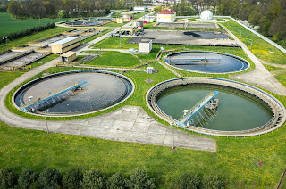
municipal water treatment plant
Municipal water treatment plant
Limit switches are devices which respond to the occurrence of a process condition by changing their contact state. In the industrial control field, their applications and product variations are almost countless. Essentially, the purpose of a limit switch is to serve as a trigger, indicating that some design condition has been achieved. The device provides only an indication of the transition from one condition to another, with no additional information. For example, a limit switch triggered by the opening of a window can only deliver an indication that the window is open, not the degree to which it is open. Most often, the device will have an actuator that is positively activated only by the design condition and mechanically linked to a set of electrical contacts. It is uncommon, but not unknown, for limit switches to be electronic. Some are magnetically actuated, though most are electromechanical. This article will focus on limit switch designs and variants used in the control and actuation of industrial process valves.
Employed in a wide range of industrial applications and operating conditions, limit switches are known for their ease of installation, simple design, ruggedness, and reliability.
Valves, devices used for controlling flow, are motion based. The movable portions of valve trim create some degree of obstruction to media flow, providing regulation of the passage of the media through the valve. It is the movement of critical valve trim elements that limit switches are used to indicate or control. The movable valve trim elements commonly connect to a shaft or other linkage extending to the exterior of the valve body. Mounting electric, hydraulic, or pneumatic actuators to the shaft or linkage provides the operator a means to drive the mechanical connection, changing the orientation or position of the valve trim and regulating the media flow. Because of its positive connection to the valve trim, the position of the shaft or linkage is analogous to the trim position and can be used to indicate what is commonly referred to as “valve position”. Limit switches are easily applied to the valve shaft or linkage in a manner that can provide information or direct functional response to certain changes in valve position.
In industrial valve terms, a limit switch is a device containing one or more magnetic or electrical switches, operated by the rotational or linear movement of the valve.
What are basic informational elements that can be relayed to the control system by limit switches? Operators of an industrial process, for reasons of efficiency, safety, or coordination with other process steps, may need answers to the following basic questions about a process control valve:
  • Is the valve open?
  • Is the valve closed?
  • Is the valve opening position greater than “X”?
  • Has the valve actuator properly positioned the valve at or beyond a certain position?
  • Has the valve actuator driven the valve mechanism beyond its normal travel limits?
  • Is the actuator functioning or failing?
Partial or complete answers to these and other questions, in the form of electrical signals relayed by the limit switch, can serve as confirmation that a control system command has been executed. Such a confirmation signal can be used to trigger the start of the next action in a sequence of process steps or any of countless other useful monitoring and control operations.

Applying limit switches to industrial valve applications should include consideration of:
  • Information Points – Determine what indications are necessary or useful for the effective control and monitoring of valve operation. What, as an actual or virtual operator, do you want to know about the real time operational status of a valve that is remotely located. Schedule the information points in operational terms, not electrical switch terms.
  • Contacts – Plan and layout a schedule of logical switches that will provide the information the operator needs. You may not need a separate switch for each information point. In some cases, it may be possible to derive needed information by using logical combinations of switches utilized for other discrete functions.
  • Environment – Accommodate the local conditions and hazards where the switch is installed with a properly rated enclosure.
  • Signal – The switch rating for current and voltage must meet or exceed those of the signal being transmitted.
  • Duty Cycle – The cycling frequency must be considered when specifying the type of switch employed. Every switch design has a limited cycle life. Make sure your selection matches the intended operating frequency for the process.
  • Auxiliary Outputs – These are additional contact sets that share the actuation of the primary switch. They are used to transmit additional signals with specifications differing from the primary signal.
  • Other Actuator Accessories – Limit switches are often integrated into an accessory unit with other actuator accessories, most of which are related to valve position. A visual local indication of valve position is a common example.
Switches and indicators of valve position can usually be provided as part of a complete valve actuation package, provided by the valve manufacturer or a third party. It is recommended that spare contacts be put in place for future use, as incorporating additional contacts as part of the original actuation package incurs comparatively little additional cost.

Employing a properly configured valve automation package, with limit switches delivering valve status or position information to your control system, can yield operational and safety benefits for the life of the unit. Good advice is to consult with a valve automation specialist for effective recommendations on configuring your valve automation accessories to maximize the level of information and control.

Succeeding: Engineer as Peacemaker

Miller Energy engineer
Make Allies, Not Adversaries

Let's take a step away from the technical, but still focus on an important aspect of our work.

As engineers involved in process measurement and control, we are accustomed to everybody else looking to us for answers and solutions. We are the people that make things work. Occasionally the pressure and stress can get a little intense and strip away some of our civility in our dealings with those around us. You may have bitter experience with this as either victim or perpetrator. It never ends well. With a private and candid self-assessment about how we view and interact with other stakeholders in our projects, we may be able to scale down some of our stress and better focus on the reality of the task at hand. Consider the points below. Comment and add a few points of your own.

You are an expert, but so are they.


Accept that, just as you have specialized knowledge that others do not, they have specialized knowledge or insight you may lack. Encourage the sharing of knowledge with those you interface with on a project. Try to be proactive and ask gently probing questions to ascertain the comprehension level of others involved in the project in various roles. Their increased understanding of key project technical concepts will promote more effective communication throughout the duration of the project. It can also help to avoid missteps in your own progress. Good people appreciate the time you take to provide basic explanation of concepts they may not fully understand, but need to know. Make valuable allies of the other project stakeholders by freely contributing your expertise. It is an investment that costs you little, but may pay immense dividends at some future time.

Everybody else's job usually looks easier than it really is.


All jobs have their own special challenges and responsibilities that generate stress. Accept the notion that you probably do not fully comprehend the burdens on those around you. Your portion of the project is certainly critical, but no more so than that of anybody else. Everybody needs to perform or nobody succeeds. Try not to view your project tasks as compartmentalized, but rather as part of the combined joint effort of all stakeholders. Help out others whenever you can. Again, make allies.  

Everybody is somebody's customer.


Whomever you deliver your work product to is your customer. The people delivering their work to you should view you as their customer. Make your customers happy by adjusting aspects of your procedures to better satisfy their needs. In a more technical sense, your modified process output becomes an improved input to their process. Small changes in your delivery may produce comparatively large returns in customer satisfaction. Allies.

Do not embarrass or demean others...especially in public settings.


Embarrassment breeds anger, a desire for revenge, and other bad and unproductive things. Avoid words and deeds that will make a coworker or stakeholder look bad in front of others. If there is a problem, if there is a mistake, try to deal with it discreetly whenever possible. Giving a someone a chance to repair a mistake before it becomes public builds value in your relationship. Certainly, there can be instances where more is at stake than someone's pride. Use good judgement to recognize when you can privately give someone an opportunity to amend a situation without causing harm.

Reach a common understanding of project scope and technical details


Your organization's management or your company's client, whatever the case may be, will likely have project expectations which will be clearly understood in their mind, but perhaps not fully described to all those tasked with specific performance. It is also possible, even probable, these same stakeholders will have misconceptions or a lack of technical knowledge about certain facets of the project. Omissions from the project specs and gaps in the common understanding of technical aspects related to the work requirements can easily turn a fairly straight forward task into a wildfire of organizational mayhem. The way in which these situations are handled must be diplomatic. Injured egos can do more damage to project harmony and progress than the facts ever will. The delivery method for the facts will likely be more crucial than the facts themselves.

It's not about being right. It's about being successful.


At our company we recognize customers are more than merely people that buy things from us. They are people to whom we contribute our time and talent to help achieve their success,... which inevitably will lead to ours. Never hesitate to let us know how we are doing, or how we can help.

Coriolis Mass Flow Meter - Operating Principle, Applications, Advantages

Coriolis flow meter by Yokogawa
Coriolis Flow Meter - Courtesy Yokogawa
Coriolis mass flow meters are widely used throughout the process measurement and control field. Their basic operating principle, combined with modern sensor and signal processing technology, provide a list of positive aspects.

Directly measure mass flow rate based on the principle of measurement.

Measure the mass flow rate with high accuracy of ±0.1%.

Provide a wide usable measurement range.

Deliver density measurement based on oscillating frequency.

Not materially impacted by fluid viscosity or density.

Coriolis flowmeters also do not need straight pipe sections upstream or downstream of the flowmeter. They also have the ability to measure non-conductive fluids. 

I have included an interesting video, produced by Yokogawa, a world class manufacturer of industrial process measurement and control instrumentation. It provides a clear and insightful illustration of the Coriolis principle and how it is used to provide accurate mass flow measurement.

Share your process measurement and control challenges with an instrumentation specialist. Combining your detailed process knowledge and their product application expertise will yield positive solutions.


Miller Energy Expanding Customer Connectivity With New Website Function

Engineering technician inspecting precision part
At Miller Energy, use website chat to connect directly with technicians
and product specialists.
Miller Energy will be rolling out real time chat on their website in early February. This new feature is another in a long line of continuous improvements the company has brought on line to better serve and connect with their customer base. On the desktop version, a chat widget will appear on every website page as a small tab on side of the display. A click of the widget will open a chat window and the visitor can type in their question or comment. Site visitors using mobile devices are afforded the same functionality.

Steve Collins, the Miller Energy website designer at CMS4i, commented on MEI's increased level of connectivity..
"The chat implementation at Miller Energy is notable because it connects customers directly with technically qualified employees that are part of the day to day company operations. Customers will be communicating with real “hands on” engineers and specialists familiar with process measurement and control, and engaged in the field on a daily basis."
Look for the chat function on the Miller Energy website in early February. Use it to get fast answers to your questions from knowledgeable and engaged industry professionals.

Safety Transmitter for Temperature and Pressure in Industrial Processes

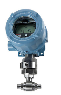
United Electric One Series industrial safety transmitter
One Series Safety Transmitters
Courtesy United Electric Controls
United Electric Controls has developed a safety transmitter that combines transmitter, safety switch, and display gauge in a single, easily deployed device. The One Series Safety Transmitter includes the manufacturer's patented self diagnostics, along with diverse and redundant signal processing that feed algorithms to detect and respond to internal faults and process abnormalities.

The safety transmitter provides a local switch that can be used for rapid emergency shutdown at the point of measurement or detection, eliminating the need to communicate with other safety controllers and await a response. The safety relay output is programmable and can handle high voltages and currents associated with shutting down control valves, compressors, and other industrial equipment.

In addition to the safety relay output, the One Series Safety Transmitter provides logic outputs that can be employed in voting logic schemes often used to produce warnings prior to a shutdown. For reliability, the unit employs no moving parts and includes self diagnostics with a local display of device status.

There is a whole lot more to learn about these "Safety right out of the box" industrial pressure and temperature transmitters. The product brochure is provided below, but you can get the latest and most detailed product and application information from a specialist in industrial process measurement and control.


Thermal Mass Flow Controller - Product Enhancement

Brooks Instrument SLA 5800 Thermal Mass Flow Meter
Newly Enhanced Thermal Mass Flow Meters
And Electronic Pressure Controllers
Courtesy Brooks Instrument
Brooks Instrument, world recognized leader in thermal mass flow controllers and mass flow meters, has improved upon its premier family of smart digital thermal mass flow controllers and meters. The newly enhanced SLA Series features:

Enhanced temperature stability
Upgraded electronics
Improved accuracy
Zero-drift diagnostics
High turndown ratio

Multiple communication protocol support, and more.

The video included below will show you all the latest improvements on this product line that has thousands of units in its installed base throughout many industries and applications.

Application assistance and detailed information is available from product specialists. Combine their product and application knowledge with your own process expertise to generate a positive outcome.

Industrial Process Application of Tunable Diode Laser Gas Analyzer

Yokogawa TDLS200 Tunable Diode Laser Gas Analyzer
Photo courtesy Yokogawa Corp.
Yokogawa continues to innovate in the industrial process measurement and control field with their TDLS200 Gas Analyzer. Based on tunable diode laser spectroscopy, these industrial instruments offer calibration stability and fast in situ measurement. They can also be applied in a manner that avoids interference from other gases present in the sample. In the company's own words...

The new Yokogawa TruePeak Tunable Diode Laser Spectroscopy (TDLS200) Analyzer is one of the most robust process analyzers available designed to make fast, accurate measurements on near-infrared absorbing gases in harsh process environments, where conditions are of high temperature or pressure, it can be used under difficult conditions including environments involving corrosive, aggressive and high particulate content materials. 


The TruePeak Tunable Diode Laser Spectroscopy (TDLS200) Analyzer is ideally suited to in-situ analysis, particularly for measurements in environments involving changing pressure or temperature. It can operate with process pressures up to 20 bar absolute and process temperature up to 1500°C, has a fast response (from 2 to 20 seconds), and is interference-free for most applications. 


It can measure Carbon monoxide (CO), from low ppm detection limits to percentage levels at process temperatures of up to 1500°C. The analyzer can also be used for measuring parts per million moisture content in corrosive and aggressive process streams including chlorine and hydrocarbons.


The industrial applications for this technology, integrated into an intuitive and user-friendly equipment package, are extensive. Included below is a white paper authored by the company that explains the operating principles, installation and configuration, and capabilities of the unit. Contact a product specialist about your gas measurement and analysis requirements. See how the capabilities of the TDLS200 can improve your process performance.


High Speed, High Performance Control for Weighing Operations

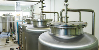
Industrial batch process tanks
Industrial Batch Process Tanks
Industrial process control implies the presence of industrial process measurement. Throughout our operations, we seek to measure "how much" of something is present. In the case of many materials, weight is the preferred measurement.


Weight is a measurement of force. We can use it as a statement of "how much" because gravity is considered constant across the planet surface. The force I measure for a batch of material in the US will, for commercial purposes, be the same force measured for that material after I ship it to somewhere else. Measurement of weight can be used for establishing proper mixing ratios of components to be combined in a particular manner. The level of material in a tank or other container can be ascertained through a measurement of weight.
In our processes, higher throughput and accuracy are always in demand.
The Vishay Precision Group's BLH/Nobel Weighing Systems operating unit manufactures a high speed, high performance control for industrial weight/force measurement applications. Their G4 line of controllers provides the user a wide range of configurable options, from multiple input channels to analog and digital outputs. The clean user interface provides access to all functions and channels and the unit is available as a freestanding desktop, DIN rail mount, or panel mount unit. There is also a model configured for harsh environments.

The video below provides a good overview of the unit and its potential applications. Contact a product specialist to receive more details, or to discuss how the G4 might be helpful to your process operation.


New Product From United Electric - Hybrid Transmitter for Industrial Use

Industrial HART Transmitter
Series One HART Transmitter
Courtesy United Electric
By mid November, United Electric will begin shipping its new One Series hybrid transmitter-switch models that include HART® Communications Protocol. The newly designed product offering includes a transmitter-only model, as well as another model providing a transmitter plus two solid-state relays. Monitoring pressure or temperature in harsh, hazardous and heavy industrial process measurement and control settings is the target application for these loop-powered transmitters. Models will include UL and ATEX approvals for Divisions 1 & 2 (Zones 1 and 2). With the introduction of the One Series, UE is declaring a number of older models obsolete. You can get a listing of the newly obsolete models from your local UE distributor.

The new combination transmitter and switch model provides a HART® 7 loop-powered transmitter, and includes two programmable solid-state relays, an improved backlit LCD display, and a separate IAWTM health status discrete output.The transmitter-only model is a HART® 7 loop-powered transmitter and also features an improved backlit LCD display.

Some operational benefits, quoted directly from United Electric's product announcement documentation:
  • With HART® 7 capability, all of the functions available with the two-button keypad are also available via the HART® Communications Protocol. Using a HART®-compatible hand held communicator or a PC with a HART® modem and appropriate asset management software, users have the ability to quickly configure the One Series, including the switching parameters, and save the configuration in their library for cloning additional controls with the same parameters. We believe this is the only Division 1 electronic switch on the market with HART compatibility!
  • If the units are connected to a control system with HART® IO allowing bi-directional communication, configuration can be performed remotely, without the need to remove the enclosure cover in a Division 1 (Zone 1) area.
  • Using a HART® capable asset management system, the comprehensive diagnostic functions of the One Series can determine the health status 24x7, saving time and money while allowing operators to focus on other critical issues.
  • For cybersecurity purposes, the HART® communications can be set to read-only mode that prohibits parameter changes from unauthorized users and creating a potentially dangerous condition.
You can explore these new products in more detail with your United Electric distributor, taking advantage of their freshly acquired new product knowledge. Find out how the advanced new features of the One Series transmitters can enhance the operation and management of your industrial process.

Recording, Data Logging, and Process Control - Consolidated or Separate Devices?

Yokogawa CX2000 Integrated Controller and Data Acquisition Device
Integrated  Controller and Data Acquisition Device
Courtesy Yokogawa
Are you a designer or builder of process control systems? Selecting hardware and componentry to provide the functionality, accuracy, and accessibility required to meet process or equipment performance demands can pose some very distinct challenges. When faced with a scope of work that includes multiple PID control loops, data recording, and networking, do you tend to favor using a collection of separate devices for each function, or a consolidated unit that integrates all of the needed functions?

I have designed many control systems throughout my career, and tended toward using separate devices initially. As I gained experience and the feedback that comes from having units in the field for a number of years, my thinking changed and my preference for integrated "single box" solutions began to predominate.

Some reasons to use a consolidated device:

  • Likely to take up less panel space than a combination of individual devices.
  • Substantially reduced wiring, cabling.
  • No tasks associated with getting individual devices to work together, if that is needed. The integrated unit comes out of the box with all of that already accomplished.
  • Reduced parts count.
  • Simplified panel wiring plan.
  • A single HMI encompassing all the provided functions.
  • Anyone, end users, service techs, trainers, quality control, that needs to learn about the operation of the system has a single instruction manual to review or learn. Since the functions all come in one unit, there is often some streamlining to the learning process.
  • OEMs may be able to use a single component to provide the necessary functions for numerous product versions, bringing measurable time savings throughout the product design, fabrication, and support functions of their organization.
  • If spares are required, there is only one.
I have enjoyed good results employing devices that combine numerous functions into a single package. There is a data sheet below, so you can see more about an industrial control, recording, networking device that packs a useful range of functions into a compact unit. 

On your next process control project, consider whether going consolidated or discrete is better for your needs. Talk to a process controls expert and get some additional input. Good solutions are out there.


Five Things to Know About Process Instrument Protection

Wireless Industrial Process Instrument
Wireless Process Instrument
Courtesy Yokogawa 
The performance of every process is critical to something or someone. Keeping a process operating within specification requires measurement, and it requires some element of control. The devices we use to measure process variables, while necessary and critical in their own right, are also a possible source of failure for the process itself. Lose the output of your process instrumentation and you can incur substantial consequences ranging from minor to near catastrophic.

Just as your PLC or other master control system emulates decision patterns regarding the process, the measurement instrumentation functions as the sensory input array to that decision making device. Careful consideration when designing the instrumentation layout, as well as reviewing these five common sense recommendations will help you avoid instrument and process downtime.

Process generated extremes can make your device fail.
Search and plan for potential vibration, shock, temperature, pressure, or other excursions from the normal operating range that might result from normal or unexpected operation of the process equipment. Develop knowledge about what the possible process conditions might be, given the capabilities of the installed process machinery. Consult with instrument vendors about protective devices that can be installed to provide additional layers of protection for valuable instruments. Often, the protective devices are simple and relatively inexpensive.

Don't forget about the weather.
Certainly, if you have any part of the process installed outdoors, you need to be familiar with the range of possible weather conditions. Weather data is available for almost anywhere in the world, certainly in the developed world. Find out what the most extreme conditions have been at the installation site....ever. Planning and designing for improbable conditions, even adding a little headroom, can keep your process up when others may be down.
Keep in mind, also, that outdoor conditions can impact indoor conditions in buildings without climate control systems that maintain a steady state. This can be especially important when considering moisture content of the indoor air and potential for condensate to accumulate on instrument housings and electrical components. Extreme conditions of condensing atmospheric moisture can produce dripping water.

Know the security exposure of your devices.
With the prevalence of networked devices, consideration of who might commit acts of malice against the process or its stakeholders, and how they might go about it, should be an element of all project designs. A real or virtual intruder's ability to impact process operation through its measuring devices should be well understood. With that understanding, barriers can be put in place to detect or prevent any occurrences.

Physical contact hazards
Strike a balance between convenience and safety for measurement instrumentation. Access for calibration, maintenance, or observation are needed, but avoiding placement of devices in areas of human traffic can deliver good returns by reducing the probability of damage to the instruments. Everybody is trained, everybody is careful, but uncontrolled carts, dropped tools and boxes, and a host of other unexpected mishaps do happen from time to time, with the power to inject disorder into your world. Consider guards and physical barriers as additional layers of insurance.

Know moisture.
Electronics must be protected from harmful effects of moisture. Where there is air, there is usually moisture. Certain conditions related to weather or process operation may result in moisture laden air that can enter device enclosures. Guarding against the formation of condensate on electronics, and providing for the automatic discharge of any accumulated liquid is essential to avoiding failure. Many instrument enclosures are provided with a means to discharge moisture. Make sure installation instructions are followed and alterations are not made that inadvertently disable these functions.

Developing a thoughtful installation plan, along with reasonable maintenance, will result in an industrial process that is hardened against a long list of potential malfunctions. Discuss your application concerns with your instrument sales engineer. Their exposure to many different installations and applications, combined with your knowledge of the process and local conditions, will produce a positive outcome.

Application Advantages of Wireless Sensors for Process Measurement and Control

Industrial Wireless Access Point
Courtesy Yokogawa
Wireless sensor technology is not new, but is still in an adoptive stage in many industries. New technologies are commonly adopted first by companies and industries that can justify the premium cost of newly released technology. The adoption process is similar to that of business computers. Early models were incredibly expensive to purchase and required a very large budget to keep operational. As time passed, the machines became less expensive to purchase and own, allowing a greater segment of the business world to justify their purchase and use. Wireless process measurement and control is following a similar path, with more and more facilities considering the potential for application of these devices.

I had always considered wireless sensing devices as a great way to be rid of cabling, but limited my thinking to fixed installations. A personal confession....Sometimes it's really hard to get my mind out of the box when I tape it shut. Anyway, I came across this application case from Yokogawa, a leading worldwide manufacturer of process measurement and control equipment and an enormous array of other industrial equipment. The case study illustrates how a tire manufacturing operation used wireless sensing technology to enhance the performance of their pressure test setup. The case study, shown below, shows the actual product part numbers used and provides a schematic and description of how the system was beneficially used. After my own reading of the case, I am now thinking of more potential applications that could benefit from a wireless configuration.

Read the case, it's short and concise. A sales engineer can provide you detailed information on the specific products used in the application. If you come up with some potential wireless process measurement applications of your own, contact an application specialist and explore the possibilities.


Know Your Control Valve Basics?

Industrial Control Valve Cutaway View
Courtesy Cashco
Understanding basic operation and function of control valves, an integral part of many industrial process control loops, is essential for the process engineer, operator, or other stakeholder. This presentation outlines control valve operation, major components, and terminology used to describe valve parts, functions, and principles of operation. A useful reference for stakeholders in need of a refresher course in order to understand what the engineers are saying, it also provides detailed illustrations, charts, and description that will prove valuable to the more technical minded.


What you will find:


  • Terminology: A glossary of terms commonly used in the control valve world.
  • Control Valve Basic Designs: Control valve classifications, cutaway illustrations showing the operating structure of different valve types, comparisons of varying valve designs.
  • Characterization and Trim Design: Flow characteristic curves and comparisons for different valve types, showing how flow responds to valve position change.
  • Control Valve Technical Considerations: FTC vs FTO, illustrations showing valve operation.
  • Force-Balance Principle: Illustration and formula explanations of this basic operating principle.
  • Actuator Basic Designs: Illustrations showing the differing arrangements for actuator operation.
  • Control Valve Unit Action: Illustrations, diagrams, and explanations of a range of valve operating conditions, including loss of electrical power and loss of instrument air supply.
  • Actuator Benchset Range: Shows practical relationship between instrument air pressure and valve ability to properly operate at various pressure conditions.
  • Valve Positioner Basics: Definition of valve positioning, reasons to use a positioner, schematic illustrations of control loops.
  • Control Loop Action: Charts and provides examples of 16 combinations of Process, Controller, Positioner, and Control Valve combinations.
  • Control Valve Packing Designs: Describes and defines packing, common problems, current state of the art. Cutaway illustrations of various packing arrangements.
  • Seat Leakage: Classifications, comparisons of different materials.


There is something of value in the document for everyone, and you will undoubtedly pick up something useful. Thanks go out to the engineers at Cashco for putting this together. You can discuss any aspect of your control valve applications with a product specialist. Your contact is always welcome.


Eliminate Glass Tube Level Gauge Maintenance Costs


Magnetic Level Indicators
Courtesy Orion Instruments
Industrial process control often requires the accurate measurement of liquid level within a tank or other vessel. There are numerous device technologies and vendors from which to choose. A recent post on this blog detailed one of the available methodologies, the magnetic level indicator. I urge you to review that short post to familiarize yourself with the operating principles and advantages of applying a magnetic level indicator, not only on future projects, but as a possible replacement of some of your existing level indication instruments.

Orion Instruments, a Magnetrol company, has authored a case study showing how the replacement of glass tube level gauges with magnetic level indicators can reap substantial cost savings over the product lifetime. The case study, included below, takes but one minute of your time to read, and delivers a compelling incentive to consider magnetic level indicators (MLI) for your new projects, even as cost saving replacements for existing glass tube level gauges.

Read the case study. Contact a product specialist to discuss your application for new or replacement level indicators.


Magnetic Level Indicators - Knowledge Base and Selection Guide

Orion Instruments Magnetic Level Indicators
Magnetic Level Indicators
Courtesy Orion Instruments
Industrial process control frequently involves the storage of liquid in vessels or tanks. Continuous and accurate indication of liquid level within the tank is an essential data point for safety and process management. While there are a number of methods and instrument types utilized to provide tank level measurement, the instrument of choice is often a magnetic level indicator, also referred to as a magnetic level gauge. Its use for providing level indication has a number of positive attributes:


  • Construction that is resistant to breakage.
  • Measuring indicators, switches, and transmitters mounted externally, without contacting the medium being measured.
  • Maintenance free operation. No regular cleaning needed.
  • Readable level indication from greater distance than glass sight gauges.
  • Magnetic level indicators can accommodate greater fluid level ranges without the need for multiple instruments.


Orion Instruments, a Magnetrol company and industry leader, has produced a comprehensive guide to magnetic level gauges, switches, transmitters, and related products. It delivers experts and newcomers an understandable and clear description of the technology and principals of operation behind magnetic level gauges and instruments. The guide also assists the reader in properly specifying and selecting the best instrument configuration for an application. A table of contents at the front of the document helps readers to quickly find the information they need.

Take a couple minutes to roll through the document and you are likely to find new and useful application tips and product information. Any questions about magnetic level indicators or your process measurement and control applications can be clearly addressed by a product specialist.


Process Gas Chromatograph with Practical Implementation of Parallel Chromatography

Process Gas Chromatograph - Yokogawa
GC8000
Process Gas Chromatograph
Courtesy Yokogawa Corp.
Gas chromatography is a common analysis tool employed in many areas of industry, including oil and gas, pharmaceutical, chemical, and others. Yokogawa Corporation of America has developed and been delivering top tier GC performance with their GC8000 Process Gas Chromatograph for use in oil and gas, and other industrial applications.

In addition to the ruggedness and reliability for which Yokogawa gas chromatographs are well known, the GC8000 brings a number of innovations and improvements to the company’s process gas chromatography product offering.

> Color touchscreen HMI for easy operation

> Advanced predictive diagnostics and software functions monitor key performance indicators during each analysis to verify analyzer is operating within proper tolerances.

> Parallel chromatography is made practical through the use of the GC Modules provided as part of the GC8000. Virtual GCs can be set up inside a single GC with GC Modules to measure multiple streams simultaneously.

The graphics below expand on this overview of the GC8000 Process Gas Chromatograph, the culmination of Yokogawa’s 55 years of experience in the field. For more detailed information, or to discuss your application specifics, contact a product specialist.


Magnetic Flow Meter – When Is It the Right Selection for Your Project?

Industrial Magnetic Flow Meter - Yokogawa
Industrial Magnetic Flow Meter
Courtesy Yokogawa Corp.
Flow measurement is a ubiquitous function in the industrial process control field. Anywhere there are pipes, somebody wants to know what, and how much, is passing through them. Fortunately for us engineers, there is a wide array of industrial flow meters capable of measuring some physical characteristic of fluid moving within a pipe that can be translated into a useful measurement of flow rate.

In industry, there are a number of different technologies used to measure a physical property related to fluid motion, referred to as magnetic, ultrasonic, vortex, Coriolis, differential pressure, and several others. Each methodology exists in the market because it may perform better or cost less when meeting certain performance requirements. This article is focused on magnetic flow meters and when they may be a good candidate for your project.

Here is a list of some of the positive attributes of magnetic flow meters.

  • Magnetic flow meters have no moving parts, always a plus.
  • General construction arrangement allows for use of an interior liner for corrosion resistance.
  • With no sensor insertions into the fluid flow, the impact of the instrument on the flow is minimized.
  • Accuracy, when compared to other technologies, is high.
  • Application to laminar, turbulent, and transitional flow profiles is permissible.
  • General insensitivity to fluid viscosity, specific gravity, temperature and pressure.
  • Magnetic flow meter technology can be applied to a very wide range of pipe sizes.
  • Device responds rapidly to changes in fluid flow.
  • Can be successfully applied to liquids containing heavy particulates.
  • Generally long service life with little maintenance.

There are, though, some points about magnetic flow meters which may make them unsuitable for your application.

  • Magnetic flow meters only work on liquids with conductivity above a certain threshold. They may be unsuitable for use with hydrocarbons and high purity water for this reason.
  • Cannot be used to measure gas flow.
  • Pipe must be grounded.
  • Typically, the pipe cross section must be filled by the fluid being measured.

This listing of positives and negatives is intended to be very general in nature. Some manufacturers may have product application solutions that overcome some of the negatives, while others may not be able to deliver all of the positives.

Your best course of action:

Use this general overview to start shaping you understanding of where magnetic flow meters may be a good option, and contact a product application specialist to discuss what you want to accomplish. Combining your process knowledge with their product knowledge should move you toward a good solution.

Industrial Flowmeter Handbook From Yokogawa

Yokogawa Industrial Magnetic Flowmeter
Magnetic Flowmeter
Courtesy Yokogawa Corp.
Measuring the volume, mass, density, and temperature of flowing fluids is a common and necessary function of industrial process control. Industrial flowmeters employ various measuring technologies to deliver accurate measurements, which are utilized to make safety, operational, and financial decisions.

Each measurement technology; magnetic, Coriolis, vortex, differential pressure, rotameter, ultrasonic, or another, has specific attributes of meter design and measurement principle making it more suitable to differing application classes. Yokogawa Corporation has summarized the suitability of the different flowmeter types for a range of process and operational conditions in a table that provides the user a consolidated comparative view of flow meter technology for almost every application. It is a useful tool that allows the engineer to quickly focus in on one or two technologies that will best suit project requirements.

Preview the handbook below, and obtain a copy of the handbook from a Yokogawa product expert, from whom you can also get expert level application assistance.


Dynamic Compensation for Static Pressure Effects in Differential Pressure Measurement

Differential Pressure Transmitter
Courtesy Yokogawa Corp.
Attaining the best available performance and accuracy from any measuring device utilized in an industrial process is always advantageous. The scale of most industrial processes is such that even small inaccuracies in process measurement produce financially tangible impact. Differential pressure measurement, with wide application in the industrial process sphere, can be improved with the addition of a means to compensate for the real world effects of static pressure upon instrument performance. Yokogawa Corporation has developed a means to dynamically compensate for static pressure effects in field measurements. The brief technical presentation below will help you understand how static pressure effects can impact your field measurements, as well as how Yokogawa’s Real-time Dynamic Compensation works to offset its impact. More detailed product and application information is available from your Yokogawa specialist.