Showing posts with label valve. Show all posts

The Schubert & Salzer Three-Way Ball Sector Valve 4080

The Schubert & Salzer Three-Way Ball Sector Valve 4080

The Three-Way Ball Sector Valve 4080 by Schubert & Salzer is a game-changer in industrial flow control. Its unique design, which includes a specialized ball sector and valve body, sets it apart from conventional three-way valves. This design allows the 4080 to achieve exceptionally high volumetric flow rates, surpassing its counterparts by approximately 20%. The result is nearly identical KVS values in all directions, enhancing performance across various uses.

The 4080 valve is a versatile solution for industrial processes, excelling at mixing or splitting flowing media. Its advanced features, including the ball sector's optimized contour, backlash-free bearing, and advanced actuators and positioners, ensure superior control accuracy. With a 90-degree positioning angle, it achieves a control rangeability of 300:1, adapting efficiently to varying operational demands.

The 4080 valve's design ensures that the forces from the flowing media are fully absorbed by the bearing shafts, requiring minimal actuation forces from either pneumatic or electric actuators. This leads to consistently low actuator torque across the entire actuation range, maintaining precise control regardless of differential pressure changes. The actuator can attach to the upper or lower shaft end, providing significant installation flexibility to accommodate diverse setups.

The 4080 valve pairs seamlessly with Schubert & Salzer's digital positioner type 8049 for enhanced performance. This combination maximizes control potential, offering additional features such as Ex and FM versions and IO-Link compatibility, which enables extensive status data for analysis and predictive maintenance.

The 4080 valve is a key component in critical temperature control and mixing processes within a variety of industries. It is particularly useful in the steel, chemical, food and beverage industries, as well as in power generation and the production of plastic and rubber products. Its robust construction from materials like stainless steel (1.4408/1.4404) and high-temperature plain bearings ensures durability and reliability under challenging conditions, handling fluid temperatures from -40°C to +220°C.

Moreover, Schubert & Salzer Control Systems GmbH ensures that the 4080 valve meets rigorous industry standards, featuring a nominal pressure rating of PN40 for DN50 and PN25 for DN65 to DN150, with a leakage class of VI according to EN 60534-4. This reliability extends to its wide range of actuator mounting options, designed according to DIN/ISO 5211 standards, and its suitability for liquids and gases.

As a leading provider of exact industrial control and stop valves, Schubert & Salzer continues to push the boundaries of valve technology. The Three-Way Ball Sector Valve 4080 exemplifies this commitment, offering unparalleled performance, efficiency, and adaptability to meet the diverse needs of modern industrial applications.

For more information about Shubert & Salzer products in NY, NJ, PA, DE, MD and OH contact Miller Energy, Inc. Call 800-631-5454 or visit https://millerenergy.com.


Use Manifold Valves With Pressure Transmitters

manifold valves for pressure transmitters and gauges
Manifold Valves for Pressure Gauges and Transmitters
Pentair - Anderson Greenwood
Pressure transmitters are generally fixed in place, but require regular access for calibration and operational testing. Unlike instruments used to measure some other process conditions, a pressure transmitter is directly connected to the process, making it's removal problematical. Manifold valves provide a compact and effective means of access and isolation needed to perform regular maintenance and calibration operations while maintaining the pressure transmitter in place.

A single pressure transmitter or gauge can be served by a simple 2-valve manifold. One valve provides isolation of the instrument from the process. The second valve opens to atmosphere on the instrument side of the isolation valve. This allows the pressure transmitter or gauge to be isolated from the process and connected to a calibration source. Here is a schematic example.
Certainly, any qualified technician can cobble together this arrangement from a pile of valves and fittings. The advantages of using a manifold valve are several.
  • High pressure rating
  • Reduced leakage potential
  • Compact size
  • Comparatively rapid installation
There are numerous manifold valve configurations to accommodate any valve and gauge requirement. Manifold valves can also be used in other applications for making effective and convenient connection arrangements between instruments and processes. Share your connectivity challenges and requirements with process instrumentation specialists, combining your process knowledge with their product application expertise to develop the best solutions.


Preparation of Control Valves For Oxygen or High Purity Service

Specialty industrial control valves
Many valves can be specially prepared for high purity or oxygen service
Oxygen is used extensively throughout a wide range of industrial processes. Medical, deep-sea, metal cutting, welding, and metal hardening are a few examples. The steel industry uses oxygen to increase capacity and efficiency in furnaces. As a synthesis gas, oxygen is also used in the production of gasoline, methanol and ammonia.

Odorless and colorless, oxygen is concentrated in atmospheric air at approximately 21%. While O2, by itself, is non-flammable, it vigorously supports combustion of other materials. Allowing oils or greases to contact high concentrations of oxygen can result in ignition and possibly explosion. Oxygen service preparation of an industrial valve calls for special cleaning processes or steps that remove all traces of oils and other contaminants from the valve to prepare for safe use with oxygen (O2). Aside from the reactive concerns surrounding oxygen, O2 preparation is also used for applications where high purity must be maintained and valves must be free of contaminants.

Gaseous oxygen is noncorrosive and may be used with a variety of metals. Stainless steel, bronze and brass are common. Liquid oxygen presents unique challenges due to cryogenic temperatures. In this case, valve bodies, stems, seals and packing must be carefully chosen.

Various types of valves are available for oxygen service, along with a wide array of connections, including screwed, socket weld, ANSI Class 150 and ANSI Class 300, DIN PN16 and DIN PN40 flanged ends. Body materials include 316 stainless steel, monel, bronze and brass. Ball and stem material is often 316 stainless steel or brass. PTFE or glass filled PTFE are inert in oxygen, serving as a common seat and seal material employed for O2 service.

Common procedures for O2 service are to carefully deburr metal parts, then meticulously clean to remove all traces of oil, grease and hydrocarbons before assembly. Valve assembly is performed in a clean area using special gloves to assure no grease or dust contaminates the valve. Lubricants compatible with oxygen must be used. Seating and leakage pressure tests are conducted in the clean area, using grease free nitrogen. Specially cleaned tools are used throughout the process. Once assembled, the valves are tested and left in the open position. A silicone desiccant pack is usually inserted in the open valve port, then the valve ports are capped. A warning label about the desiccant pack's location is included, with a second tag indicating the valve has been specially prepared for oxygen service. Finally, valves are individually sealed in polyethylene bags for shipment and storage. Different manufacturers may follow slightly differing protocols, but the basics are the same. The valve must be delivered scrupulously contaminant free.

The O2 preparation of valves is one of many special production variants available to accommodate your special application requirements. Share your valve requirements and challenges with a valve specialist to get the best solution recommendations.

Process Automation: Valve Actuator Limit Switches

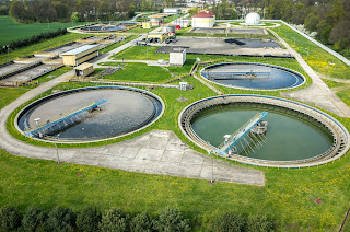
municipal water treatment plant
Municipal water treatment plant
Limit switches are devices which respond to the occurrence of a process condition by changing their contact state. In the industrial control field, their applications and product variations are almost countless. Essentially, the purpose of a limit switch is to serve as a trigger, indicating that some design condition has been achieved. The device provides only an indication of the transition from one condition to another, with no additional information. For example, a limit switch triggered by the opening of a window can only deliver an indication that the window is open, not the degree to which it is open. Most often, the device will have an actuator that is positively activated only by the design condition and mechanically linked to a set of electrical contacts. It is uncommon, but not unknown, for limit switches to be electronic. Some are magnetically actuated, though most are electromechanical. This article will focus on limit switch designs and variants used in the control and actuation of industrial process valves.
Employed in a wide range of industrial applications and operating conditions, limit switches are known for their ease of installation, simple design, ruggedness, and reliability.
Valves, devices used for controlling flow, are motion based. The movable portions of valve trim create some degree of obstruction to media flow, providing regulation of the passage of the media through the valve. It is the movement of critical valve trim elements that limit switches are used to indicate or control. The movable valve trim elements commonly connect to a shaft or other linkage extending to the exterior of the valve body. Mounting electric, hydraulic, or pneumatic actuators to the shaft or linkage provides the operator a means to drive the mechanical connection, changing the orientation or position of the valve trim and regulating the media flow. Because of its positive connection to the valve trim, the position of the shaft or linkage is analogous to the trim position and can be used to indicate what is commonly referred to as “valve position”. Limit switches are easily applied to the valve shaft or linkage in a manner that can provide information or direct functional response to certain changes in valve position.
In industrial valve terms, a limit switch is a device containing one or more magnetic or electrical switches, operated by the rotational or linear movement of the valve.
What are basic informational elements that can be relayed to the control system by limit switches? Operators of an industrial process, for reasons of efficiency, safety, or coordination with other process steps, may need answers to the following basic questions about a process control valve:
  • Is the valve open?
  • Is the valve closed?
  • Is the valve opening position greater than “X”?
  • Has the valve actuator properly positioned the valve at or beyond a certain position?
  • Has the valve actuator driven the valve mechanism beyond its normal travel limits?
  • Is the actuator functioning or failing?
Partial or complete answers to these and other questions, in the form of electrical signals relayed by the limit switch, can serve as confirmation that a control system command has been executed. Such a confirmation signal can be used to trigger the start of the next action in a sequence of process steps or any of countless other useful monitoring and control operations.

Applying limit switches to industrial valve applications should include consideration of:
  • Information Points – Determine what indications are necessary or useful for the effective control and monitoring of valve operation. What, as an actual or virtual operator, do you want to know about the real time operational status of a valve that is remotely located. Schedule the information points in operational terms, not electrical switch terms.
  • Contacts – Plan and layout a schedule of logical switches that will provide the information the operator needs. You may not need a separate switch for each information point. In some cases, it may be possible to derive needed information by using logical combinations of switches utilized for other discrete functions.
  • Environment – Accommodate the local conditions and hazards where the switch is installed with a properly rated enclosure.
  • Signal – The switch rating for current and voltage must meet or exceed those of the signal being transmitted.
  • Duty Cycle – The cycling frequency must be considered when specifying the type of switch employed. Every switch design has a limited cycle life. Make sure your selection matches the intended operating frequency for the process.
  • Auxiliary Outputs – These are additional contact sets that share the actuation of the primary switch. They are used to transmit additional signals with specifications differing from the primary signal.
  • Other Actuator Accessories – Limit switches are often integrated into an accessory unit with other actuator accessories, most of which are related to valve position. A visual local indication of valve position is a common example.
Switches and indicators of valve position can usually be provided as part of a complete valve actuation package, provided by the valve manufacturer or a third party. It is recommended that spare contacts be put in place for future use, as incorporating additional contacts as part of the original actuation package incurs comparatively little additional cost.

Employing a properly configured valve automation package, with limit switches delivering valve status or position information to your control system, can yield operational and safety benefits for the life of the unit. Good advice is to consult with a valve automation specialist for effective recommendations on configuring your valve automation accessories to maximize the level of information and control.