Summary of Technologies Used For Continuous Liquid Level Measurement in Industrial Process Control

non-contact radar liquid level transmitter
Non-contact radar liquid level transmitter
Courtesy Magnetrol
Automated liquid processing operations in many fields have requirements for accurate and reliable level measurement. The variety of media and application criteria demand continuous improvement in the technology, while still retaining niches for older style units utilizing methods that, through their years of reliable service, inspire confidence in operators.

Here is a synopsis of the available technologies for instruments providing continuous liquid level measurement. All are generally available in the form of transmitters with 4-20 mA output signals, and most are provided with additional outputs and communications. What is notably not covered here are level switches or level gauges that do not deliver a continuous output signal corresponding to liquid level.

Whether considering a new installation or upgrading an existing one, it can be a good exercise to review several technologies as possible candidates for a project. None of the technologies would likely be considered the best choice for all applications. Evaluating and selecting the best fit for a project can be facilitated by reaching out to a product application specialist, sharing your applications challenges and combining your process knowledge with their product expertise to develop an effective solution.

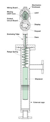
Displacer – A displacer is essentially a float and a spring that are characterized for a particular liquid and range of surface level movement. The displacer moves in response to liquid level, changing the location of a core connected to the displacer by a stem. The core is within a linear variable differential transformer. The electrical output of the transformer changes as the core moves.

Guided Wave Radar – A radar based technology that uses a waveguide extending into the liquid. The radar signal travels through the waveguide, basically a tube. The liquid surface level creates a dielectric condition that generates a reflection. Calculations and processing of the emitted and returned signals provide a measure of distance to the liquid surface. No moving parts.

Magnetostrictive – A method employing measurement of the transit time of an electric pulse along a wire extending down an enclosed tube oriented vertically in the media. A magnetic float on the exterior of the tube moves with the liquid surface. The float’s magnetic field produces the return signal to the sensor. Processing the time from emission to return provides a measure of distance to the liquid surface.

Pulse Burst Radar - A radar based technology employing emissions in precisely timed bursts. The emission is reflectex from the liquid surface and transit time from emission to return is used to determine distance to media surface.  Not adversely impacted by changes in media conductivity, density, pressure, temperature. No moving parts.

Frequency Modulated Continuous Wave Radar – Another radar based technology that employs a radar signal that sweeps linearly across a range of frequencies. Signal processing determines distance to media surface.  Not adversely impacted by changes in media conductivity, density, pressure, temperature. No moving parts.

RF Capacitance - As media rises and falls in the tank, the amount of capacitance developed between the sensing probe and the ground reference (usually the side metal sidewall) also rises and falls. This change in capacitance is converted into a proportional 4-20 mA output signal. Requires contact between the media and the sensor, as well as a good ground reference. No moving parts.

Ultrasonic Non-Contact – Ultrasonic emission from above the liquid is reflected off the surface. The transit time between emission and return are used to calculate the distance to the liquid surface. No contact with media and no moving parts.

Differential Pressure – Pressure sensor at the bottom of a vessel measures the pressure developed by the height of the liquid in the tank. No moving parts. A variation of this method is often called a bubbler, which essentially measures hydrostatic pressure exerted on  the gas in a tube extending into the contained liquid. It has the advantage of avoiding contact between the measuring instrument parts, with the exception of the dip tube, and the subject liquid.

Laser - Probably one of the latest arrivals on the liquid level measurement scene, laser emission and return detection is used with time interval measuring to accurately determine the distance from the sensor source to the liquid surface.

Load Cell - A load cell or strain gauge can be incorporated into the support structure of the liquid containing vessel. Changes in the liquid level in the vessel are detected as distortions to the structure and converted, using tank geometry and specific gravity of the liquid.

All of these technologies have their own set of attributes which may make them more suitable to a particular range of applications. Consulting with a product specialist will help determine which technologies are the best fit for your application.


Diaphragm Pressure Gauges for Industrial Process Measurement

diaphragm pressure gauge for industrial process measurement
Example of a diaphragm pressure gauge
Courtesy Wika
Diaphragm pressure gauges, like every device and instrument intended for use in industrial process measurement and control, have their own set of attributes making them an advantageous choice for some range of applications. Silvia Weber, product manager at Wika, a globally recognized leader in the field of pressure and temperature gauges, wrote an article for Process Worldwide (process-worldwide.com/) about diaphragm pressure gauges.

The article is included below and provides a comparison of the differences between Bourdon tube and diaphragm operating mechanisms, focusing on design and operational features of diaphragm pressure gauges and the range of application criteria for which they may be the best choice.

Pressure gauges are utilized in most operations where fluids are moved through a system. Gauges, though mechanical in operation, remain a mainstay of fluid operations because of their reliability, local display, ruggedness, and lack of reliance on electric power for operation. There are countless pressure gauge configurations to suit every application. Specifying the best gauge configuration for an application is accomplished by combining your process knowledge with the application expertise of a product specialist.


Protect Valuable Pressure Gauges and Transmitters With a Pressure Limiting Valve

pressure limiting valve for gauge or transmitter protection
Pressure limiting valve provides gauge
or transmitter protection from spikes
Courtesy Mid-West Instruments
Pressure gauges and transmitters, commonly found in fluid process control operations, are vulnerable to damage from transient spikes in system pressure that may range beyond the instrument's working range. These pressure spikes can impact instrument calibration, or even render the instrument or gauge inoperative. The cost of replacing gauges or transmitters is substantial enough to warrant the use of protective devices to prevent exposure to pressure spikes.

Mid-West Instruments manufactures a line of pressure limiting valves specifically intended for use with pressure gauges and transmitters. The Model 200 pressure limiting valve prevents instrument over-range and has an adjustable needle valve to dampen pulsation. The valve and be used with all types of instruments and pressure gauges, is suitable for mounting in any position, and is available in a range of materials for body and seals.

The document below provides more product detail, as well as installation and setup instructions. Providing a useful measure of protection for pressure gauges and transmitters is a simple operation. Reach out to product application specialists for help in formulating effective solutions.


Industrial Process Gauges - New Product Guide

industrial pressure gauge
One of the many pressure gauge versions
employed throughout industry
Courtesy Ametek - U.S. Gauge
Even with the large growth in the use of electronic measurement instruments throughout the process control sphere, mechanical gauges and indicators remain an important part of process measurement and control operations.

A broad line of industrial gauges and diaphragm seals is available from U.S. Gauge. The company has consolidated its offering into a product guide that provides simple and quick reference to the various product series.

For pressure:

  • Process Gauges
  • Liquid Filled Gauges
  • Test Gauges
  • General Equipment Gauges
  • Special Application Gauges

For temperature:

  • Adjustable Bimetallic Thermometers
  • Thermowells
  • Industrial Bimetallic Thermometers
  • Multi-Angle Industrial Thermometers
  • Digital Thermometers
  • Glass Tube Thermometers
The product guide also includes diaphragm seals and a range of electronic indicators, as well.

The guide illustrates gauges for every industrial application. Share your process measurement and control challenges with product application specialists, combining your process knowledge with their product application expertise to develop effective solutions.


Basic Guide to Understanding Pressure

absolute pressure transmitter for industrial process measurement control
One style of absolute pressure transmitter
Courtesy Yokogawa
The impact of pressure on industrial processes would be difficult to understate. Pressure is an element of process control that can affect performance and safety. Understanding pressure concepts and how to effectively measure pressure within a process are key to any operator's success.

Yokogawa, a globally recognized leader in process measurement and control, has made available a handbook on pressure that covers a range of useful topics. The content starts with the very basic concepts and moves quickly to practical subjects related to process measurement and control.

The handbook will prove useful to readers at all levels of expertise. Share your process measurement challenges with application specialists, combining your process knowledge with their product application expertise to develop effective solutions.


Specialty Valves for Biotech and Pharma Applications

stainless steel sanitary ball valve with handle cutaway view
Stainless steel ball valve for sanitary applications
Courtesy Habonim USA
Sanitary fluid process operations require the use of valves with unique characteristics that make them suitable for use. Materials of construction, FDA approved materials for seals, clean draining, and no retainage of the process fluid are some of the requirements for sanitary valves. Pharma and other bioprocess industries, including food and beverage, will also have stringent requirements for sterilizing or cleaning in place.

One manufacturer, Habonim, a globally recognized manufacturer of high quality ball valves, offers a complete line of ball valves specifically designed for sanitary process applications.

The TuBore valve series is available in line sizes from 1/4" to 6" with clamped or welded connections and available with manual operator, pneumatic or electric actuation.

The datasheet included below provides more detail and specifications. Share your sanitary fluid process control requirements and challenges with product specialists. Combining your process knowledge with their product application expertise will produce effective solutions.

V-Cone® Flow Meter Conditions Flow For Accurate Measurement


Accurate measurement of fluid flow is a process requirement in many industrial operations. There are numerous methods employed in the measurement of fluid flow, of which the McCrometer V-Cone® is one entry with very particular advantages. Whether the application involves liquid, steam, or gas, this flow meter design, with its own flow conditioning built in, provides exceptional differential pressure flow measurements in a space saving format.

The video provides a clear illustration of how the V-Cone® design conditions fluid flow in order to provide better DP measurement performance. Share your flow measurement challenges with application specialists, combining your process expertise with their depth of product application knowledge to develop effective solutions.

Electronic Displacer Liquid Level Transmitter - How it Works, When to Use It

Displacer liquid level transmitter diagram
Electronic displacer liquid
level transmitter using spring
technology
Courtesy Magnetrol
An electronic displacer liquid level transmitter is intended for industrial applications requiring the continuous measurement of liquid level in a tank, vessel, or other containing space.

Magnetrol, a globally recognized leader in the design and production of level measurement instrumentation, describes the operating principle of their Digital E3 Modulevel® displacer level transmitter:
Electronic displacer level transmitter technology operates by detecting changes in buoyancy force caused by liquid level change. These forces act upon the spring supported displacer causing vertical motion of the core within a linear variable differential transformer.
The movement of the core within the LVDT generates an electrical signal which is further processed and serves as the output of the transmitter. The unit is designed to be externally mounted on a tank. Isolation valves are recommended.

The spring technology employed as a counterforce to the buoyancy of the displacer results in a stable signal that is not impacted greatly by vibration, agitation, or turbulence of the measured liquid.

The video below provides more detail, covering the features and advantages of this level measurement technology and the Magnetrol instrument. Share your level measurement challenges and requirements with a product application specialist. The combination of your process knowledge and their product application expertise will produce effective solutions.

Tank Blanketing Valve Function and Useful Features

tank blanketing valve
Tank Blanketing Valve
Caschco - Valve Concepts
The filling of vapor space in a liquid containing tank with a gas is referred to as "tank blanketing", and sometimes "padding". Specialized valves are available, designed to simplify the incorporation of a tank blanketing function in an operation.

Often, the gas employed to fill the vapor space in a tank is nitrogen. The purpose of blanketing can vary, but generally involves preservation of the stored product or safety. In both cases, one goal is to keep oxygen levels in the vapor space sufficiently low to inhibit ignition of flammable products, or minimize oxidation and its impact on stored product quality. The inflow of blanketing gas can also be used to keep the tank under positive pressure relative to the surrounding space, considered to harbor contaminants which could otherwise leak into the tank.


What are some functions of a tank blanketing valve?


  • Maintain positive pressure in the tank at a selected setpoint.
  • Provide gas control at very low flow rates, or close bubble tight, when tank liquid level is static.
  • Adjust gas flow to compensate for the maximum liquid draw down rate.
  • Provide sufficient closure to prevent supply gas from excessively pressurizing tank.
Blanketing valves are used in conjunction with vents to provide a full range of control over the pressure and content of the vapor space within a tank. A single valve solution eases the design and component selection burden of amassing individual components and combining them into a working assembly. Some useful features of a blanketing valve include:
  • Bubble tight shutoff to prevent wasting of purge gas.
  • Self cleaning flow path design.
  • Pressure balanced pilot, so supply pressure fluctuations do not impact the setpoint.
  • Setpoint not appreciably affected by changes in temperature.
  • Low maintenance requirements, including complete access to valve internals without removing the valve from the tank.
More detail, including a description of the elements required for proper valve sizing, is found in the document below. Share your fluid process measurement and control challenges with application specialists, combining your process experience and knowledge with their product application expertise to develop effective solutions.

Refrigerated Air Dryer for Compressed Air

refrigerated dryer for compressed air low dewpoint
Refrigerated Dryer for Compressed Air
Wilkerson Corporation
Compressed air, a common source of power in many industrial settings, functions best when treated in a number of ways to remove contaminants that can damage or impair downstream devices and equipment. One contaminant of concern is moisture.

When ambient air is compressed, its temperature increases, but also does the ratio of water per unit of air volume. This results in a compressed air supply with what may be an unacceptably high dew point. Dew point is the temperature at which air is saturated, and cooling air below its dew point will result in the formation of condensate (liquid water). As compressed air is consumed by usage equipment, the air pressure drops, along with the temperature. These condition changes, and others, can result in condensate formation in the compressed air system and connected equipment. This is generally considered a negative development, as the presence of excessive moisture can lead to line freezing, corrosion, excessive equipment wear, and malfunction.

There are a number of methods and technologies available to reduce the absolute moisture content of compressed air. Each has its own set of positive, as well as limiting, aspects that dictate the best way to apply the technology.

Refrigerated air dryers employ essentially the same principle used to dehumidify air in occupied spaces within commercial buildings and residences. The incoming compressed air is cooled through the use of a mechanical refrigeration system. Cooling the compressed air results in condensing a portion of it's moisture content. The chilled air is then used to pre-cool the incoming compressed air, boosting the cooling system effectiveness and increasing the temperature of the discharge air. This increase in the discharge air temperature is also helpful in preventing condensate formation on the downstream system piping.

The refrigerated air dryer is a single part of what should be a total approach to compressed air quality. Here is a schematic example.

schematic compressed air treatment components with refrigerated dryer
A refrigerated dryer is one of several components that remove contaminants from compressed air systems
More information and detail is provided in the document below. Share your compressed air system requirements and challenges with application experts, combining your process experience and knowledge with their product application expertise to develop effective solutions.


Solenoid Valves - The Operational Basics

industrial solenoid operated valves
Industrial Solenoid Valves
Magnatrol
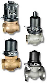
A solenoid is an electric output device that converts electrical energy input to a linear mechanical force.

At the basic level, a solenoid is an electromagnetic coil and a metallic rod or arm. Electrical current flow though the coil produces a magnetic field, the force of which will move the rod. The movable component of the solenoid is linked to, or part of, the operating mechanism of another device. This allows the switched electrical output of a controller to regulate mechanical movement in another device and cause a change in its operation. A common solenoid application is the operation of valves.

A plunger solenoid contains a movable ferrous rod, sometimes called a core, enclosed in a tube sealed to the valve body and extending through the center of the electromagnetic coil. When the solenoid is energized, the core moves to its equilibrium position in the magnetic field. The core is also a functional part of valve operation. It's repositioning causes a designed changed in the valve operating status (open or close). There are countless variants of solenoid operated valves exhibiting particular operating attributes designed for specific types of applications. In essence, though, they all rely on the electromechanical operating principle outlined here.

A solenoid valve is a combination of two functional units.
  • The solenoid (electromagnet) described above.
  • The valve body containing one or more openings, called ports, for inlet and outlet, and the valve interior operating components.
Flow through an orifice is controlled by the movement of the rod or core. The core is enclosed in a tube sealed to the valve body, providing a leak tight assembly. A controller energizing or de-energizing the coil will cause the valve to change operating state between open and closed, regulating fluid flow. There are almost countless variants of solenoid operated valves, specifically tailored for applications throughout industrial, commercial, and institutional operations.

The document provided below illustrates a portion of the broad array of solenoid valves available for industrial control applications. There are also some good cutaway illustrations showing the internal operating valve parts. Share your valve requirements and challenges with an application specialist. Combining your process application knowledge with their product expertise will produce effective solutions.

Use Electronic Pressure Controllers in Your Research Process Loop to Eliminate Droop, Boost, and Hysteresis

(re-blogged with permission from Brooks Instrument)
Gas pressure control is critical in many applications like life sciences and chemical/petrochemical research where flow is an integral part of the process. Brooks Instrument electronic pressure controllers can be used as they require flow to function. Compared to using a mechanical pressure regulator, electronic pressure controllers eliminate droop, boost and hysteresis, offering stable pressure control.

There are two configurations available for pressure control – upstream and downstream. This terminology is somewhat unique to Brooks Instrument electronic pressure controllers.

Downstream vs. Upstream Pressure Control

downstream vs upstream pressure control diagram
Downstream pressure controllers maintain the pressure downstream of the device itself, increasing flow to increase the pressure and decreasing flow to decrease the pressure. For this reason, this is called direct acting. This configuration is commonly called a standard pressure regulator. A downstream pressure controller acts very similar to a typical mass flow controller because they are both direct acting.

Upstream pressure controllers maintain the pressure upstream of the device itself, increasing flow to reduce the pressure and decreasing flow to increase the pressure. For this reason, this is called reverse acting. This configuration is commonly called a back pressure regulator in the industry.

Selecting and Sizing an Electronic Pressure Controller

The following information is required to select and size a Brooks Instrument electronic pressure controller:
  • Process gas
  • Maximum flow rate being used to maintain pressure -The “sweet spot” for pressure control is between 100 SCCM and 5 SLPM.
  • Calibration pressure (maximum pressure to be controlled)
  • Reference pressure (for upstream controllers the reference pressure is the downstream pressure and for downstream controllers the reference pressure is the upstream pressure)
As long as flow is present in a process you will typically find the need for some type of pressure control. Vessel sizes up to 30 liters commonly use flow rates up to 3 SLPM during their process steps. Brooks Instrument pressure controllers are a perfect fit for these services, offering stable pressure control with no droop, boost or hysteresis, which are commonly experienced when using a mechanical pressure regulator.


Typical Bioreactor Process Using an Upstream Pressure Controller

Magnetic Liquid Level Gauges

magnetic level indicator with auxiliary tube for guided wave radar
Magnetic level indicator with supplemental
guided wave radar instrument
Gemini Model - Magnetrol
Magnetic liquid level gauges are an excellent alternative to sight glass level gauges for many process measurement applications. Their reliable performance and adaptability has made them the primary choice in a wide variety of industrial settings.

Essentially, a magnetic level gauge or magnetic level indicator, is a sight glass with enhancements that provide better readability and a form factor that enables the inclusion of additional level monitoring functions on the same device. Where a sight glass requires operator proximity to read liquid level, the magnetic level gauge's indicating scale, or flags, can be clearly viewed from a considerable distance. A sight glass gauge can also be hindered by difficulties in visually determining liquid level because of deterioration of the glass surface or properties of the liquid. Magnetic level gauges remove the need to observe the liquid directly by incorporating a float device within a tube connected to the liquid containing vessel. As the float moves in response to liquid level changes, its magnet causes the indicator flags on the scale to rotate and display either a black face to indicate no liquid present, or a colored face.

Magnetic level indicators are available with numerous options, including armored casings to protect the tube and float arrangement and limit switches to signal the attainment of specific level conditions. Combining a MLI with another level measurement technology, such as guided wave radar or magnetostrictive, can provide an analog process signal representing liquid level and serve as a redundant measuring device for critical applications.

The document included below provides illustrated detail about the devices and their proper application. Share your process measurement requirements and challenges with instrumentation experts. The combination of your process knowledge and their product application expertise will produce effective solutions.


Comparison of RTD and Thermocouple for Process Measurement

industrial temperature sensor rtd or thermocouple
Industrial Temperature Sensor
Courtesy Wika
Proper temperature sensor selection is key to getting useful and accurate data for maintaining control of a process. There are two main types of temperature sensors employed for industrial applications, thermocouple and resistance temperature detector (RTD). Each has its own set of features that might make it an advantageous choice for a particular application.

Thermocouples consist of a junction formed with dissimilar metal conductors. The contact point of the conductors generates a small voltage that is related to the temperature of the junction. There are a number of metals used for the conductors, with different combinations used to produce an array of temperature ranges and accuracy. A defining characteristic of thermocouples is the need to use extension wire of the same type as the junction wires, in order to assure proper function and accuracy.
Here are some generalized thermocouple characteristics.
  • Various conductor combinations can provide a wide range of operable temperatures (-200°C to +2300°C).
  • Sensor accuracy can deteriorate over time.
  • Sensors are comparatively less expensive than RTD.
  • Stability of sensor output is not as good as RTD.
  • Sensor response is fast due to low mass.
  • Assemblies are generally rugged and not prone to damage from vibration and moderate mechanical shock.
  • Sensor tip is the measuring point.
  • Reference junction is required for correct measurement.
  • No external power is required.
  • Matching extension wire is needed.
  • Sensor design allows for small diameter assemblies.
RTD sensors are comprised of very fine wire from a range of specialty types, coiled within a protective probe. Temperature measurement is accomplished by measuring the resistance in the coil. The resistance will correspond to a known temperature. Some generalized RTD attributes:
  • Sensor provides good measurement accuracy, superior to thermocouple.
  • Operating temperature range (-200° to +850°C) is less than that of thermocouple.
  • Sensor exhibits long term stability.
  • Response to process change can be slow.
  • Excitation current source is required for operation.
  • Copper extension wire can be used to connect sensor to instruments.
  • Sensors can exhibit a degree of self-heating error.
  • Resistance coil makes assemblies less rugged than thermocouples.
  • Cost is comparatively higher
Each industrial process control application will present its own set of challenges regarding vibration, temperature range, required response time, accuracy, and more. Share your process temperature measurement requirements and challenges with a process control instrumentation specialist, combining your process knowledge with their product application expertise to develop the most effective solution.

Ultrasonic Contact Level Switches Provide Reliable Overfill Protection

ultrasonic contact type level switches
Echotel® Ultrasonic Level Switches
Magnetrol
Requirements for safety regulation compliance continue to grow. Business operators want increased levels of risk aversion and contingency management. In industrial settings where fluids are processed or stored, meeting these goals calls for new layers of protection and redundancy for existing layers.

Tank overfill is a serious concern of any fluid processor. Providing multiple methods of measuring tank or vessel fluid level provides substantially greater assurance against overfill. One scheme involves using a continuous level measurement instrument, such as guided wave radar, to provide the real time tank level signal and an ultrasonic level switch as a tank overfill indicator.

The operating principal of an ultrasonic level switch is quite simple. A transducer sends an ultrasonic pulse across a gap. When liquid media is present in the gap, the sound wave is transmitted with little attenuation across the gap and detected. When liquid media does not fill the gap, the sound wave is strongly attenuated and fails to transmit across the gap.

Tuning fork level switches are commonly applied as the overfill detection device, but Magnetrol, a recognized global innovator in level measurement, feels they have a better solution with their Echotel® ultrasonic level switches. The video below provides an illustration of how the ultrasonic level switches can be applied, as well as a comparison between ultrasonic and tuning fork methods.

Share your level measurement requirements and challenges with a product application specialist. The combination of your process expertise and their product application skill will produce an effective solution.


Use Manifold Valves With Pressure Transmitters

manifold valves for pressure transmitters and gauges
Manifold Valves for Pressure Gauges and Transmitters
Pentair - Anderson Greenwood
Pressure transmitters are generally fixed in place, but require regular access for calibration and operational testing. Unlike instruments used to measure some other process conditions, a pressure transmitter is directly connected to the process, making it's removal problematical. Manifold valves provide a compact and effective means of access and isolation needed to perform regular maintenance and calibration operations while maintaining the pressure transmitter in place.

A single pressure transmitter or gauge can be served by a simple 2-valve manifold. One valve provides isolation of the instrument from the process. The second valve opens to atmosphere on the instrument side of the isolation valve. This allows the pressure transmitter or gauge to be isolated from the process and connected to a calibration source. Here is a schematic example.
Certainly, any qualified technician can cobble together this arrangement from a pile of valves and fittings. The advantages of using a manifold valve are several.
  • High pressure rating
  • Reduced leakage potential
  • Compact size
  • Comparatively rapid installation
There are numerous manifold valve configurations to accommodate any valve and gauge requirement. Manifold valves can also be used in other applications for making effective and convenient connection arrangements between instruments and processes. Share your connectivity challenges and requirements with process instrumentation specialists, combining your process knowledge with their product application expertise to develop the best solutions.


Thermal Dispersion Flow Meter For Compressed Air and Nitrogen Measurement

thermal dispersion mass flow meter
Thermal Dispersion Flow Meter
Magnetrol
Monitoring compressed air usage in a factory or other operation where it is consumed is essential for proper system maintenance and attainment of energy efficiency goals. The ability to track down leaks and monitor compressed air usage enables stakeholders to work toward maximizing the return on an asset with substantial initial and operating costs.

Easy installation and simplicity of operation are advantages for any instrument applied in this manner, making compressed air flow measurement a good application for a thermal dispersion flow meter. With no moving parts and a simple operating principal, a thermal dispersion flow meter can be quickly installed and put into operation. A digital display of the flow measurement provides local information, and a networking connection or other signal output can provide for remote or centralized monitoring and data collection.

A cut sheet is included below that provides detail on technological, operational, and installation aspects of this simple and effective instrument. Share your flow measurement challenges with application experts, combining your own process knowledge with their product application expertise to develop cost effective solutions.


Setting Up the United Electric Controls Series One Safety Transmitter

Here is a two part tutorial showing how to setup your United Electric Series One Safety Transmitter. If you need any additional help or product information, reach out to a product specialist.

Part One Video

Part Two Video

Safety Transmitters For Temperature and Pressure

safety transmitter for industrial process control pressure temperature
Series One Safety Transmitter
United Electric Controls
Industrial history is replete with examples of catastrophic accidents. New safety technologies exist today that can prevent or mitigate mishap and disaster in fluid processing and other operations. Modern philosophy of plant safety brings a focus on a proactive approach. Process operators have a new sense of urgency to bring increased levels of safety to their operations.

The United Electric Controls (UE) Series One is a SIL-certified (Safety Integrity Level) transmitter designed solely for safety, alarm, and shutdown. With reliability, speed, and reduced nuisance trips an integral part of its design, the Series One is suitable for application in new installations, or easily integrated into existing operations.

A typical safety loop consists of sensors (such as a pressure or temperature transmitter), controllers, and final control elements. Most SIL-rated pressure transmitters require 300ms to communicate with the controller, then up to 500ms for the controller to send a signal to the final control element (such as a valve). This combined response time may insufficient for some applications. Incorporating the One Series Safety Transmitter, directly connected to the final control element, the total signal time is reduced to 100ms - a large and significant time savings when safe operating conditions have been breached. When used with blowers, pumps and compressors, the One Series makes up a complete safety system with a self-contained sensor, controller, and final control element (the switch) capable of SIL2 without additional safety instrumented function (SIF) components.

The below document provides detailed information about the Series One. Share your process safety challenges with the instrumentation specialists and combine your process knowledge with their product application expertise to produce effective solutions.


Opportunity For Improving Power Plant Heat Rate

electric power plant
Opportunities for improving efficiency at power plants
The large scale of most power plants provides a environment in which financial justification, or payback, of attempts to improve energy consumption can be justified. Even small improvements in efficiency can yield very substantial returns. The challenge to engineering and management is to select the projects which have the best overall probability of success and can be integrated into the process with the least amount of disturbance.

One area of the steam cycle that may be a candidate for improvement is the feedwater heater. This device is essentially a shell and tube heat exchanger used to recover waste heat from the process and use it to preheat boiler feedwater. Maintaining the correct liquid level in the feedwater heater is a key element of extracting maximum performance. Magnetrol, a globally recognized leader in the development of level measurement equipment, has produced a video showing how their technology can be used in an advantageous manner to others in regulating feedwater heater liquid level and achieving maximum efficiency.


Handbook on pH and ORP Measurement

pH ORP analyzer transmitter
Dual input pH analyzer and transmitter
Courtesy Yokogawa
Measurement of pH/ORP is a common operation throughout a number of industries. Obtaining true measurements and making correct interpretation of the results can prove challenging without solid working knowledge of the methodology and procedure involved. Certain effects have the ability to cause problems if not taken into consideration.

The book provided below, authored and provided by Yokogawa Electric Corporation, provides a comprehensive understanding of pH/ORP measurement and how to achieve reliable results. Basic information on the principles of measuring pH/ORP, construction of the sensing elements, and their basic use in process applications is provided.

A part of achieving accurate and reliable pH/ORP measurements includes the provision of sufficient electrode strorage conditions and proper maintenance. Prevention of common errors during maintenance and storage, as well as consistent detection of loop failures is important. This book describes how to avoid pitfalls and detect failures.

The book is accompanied with a frequently asked question and answer section as well as an appendix that includes helpful information like a Chemical Compatibility Table and a Liquid-Application-Data-Sheet, which can be used to describe the user’s application.


Miller Energy Introductory Video

Miller Energy is a Manufacturer's Representative and Distributor of Industrial Instrumentation and Process Control Equipment. Since 1958, Miller been committed to exceeding our customers expectations by providing an unparalleled level of customer service and local technical support. Miller Energy maintains two office locations in NJ and PA. The South Plainfield, NJ operation services the areas of Northern NJ, New York, and Fairfield County Connecticut and serves as our corporate headquarters. The Exton PA office serves the areas of Southern NJ, Eastern PA, Delaware and Maryland.


Safety Transmitters Achieve Safety Goals With Reduced Cost and Complexity


safety transmitter for temperature, pressure, differential pressure applications in industrial process control
Series One Safety Transmitter
United Electric Controls
Process safety experts continually seek sustainable ways to improve the performance of safety critical loops, achieving risk reduction and safety goals in a cost-effective manner. Some view a reduction in complexity of safety related protocols to be a positive development. Traditional or historical approaches to deploying full blown safety systems were generally associated with great expense and high complexity, and still came up short on delivering the needed levels of risk reduction. Process control device and equipment manufacturers have responded with newer technologies and products that better address the safety needs of industrial processing.

In sensor subsystems, United Electric’s certified safety transmitter for pressure or temperature provides a less costly, simple path for process designers, instrument and control engineers, and maintenance personnel. The Series One Safety Transmitters combine several useful safety and monitoring functions into a single, easy to deploy device. Products are available for gauge pressure, differential pressure, and temperature applications. In addition to a 4-20 mA process variable output, the Series One has an embedded programmable high-capacity relay certified as a safety variable output. The Series One Safety Transmitter provides designers the option of a hard wired trip in less than 100 milliseconds, with a tenth of a percent repeatability, along with the monitoring functions of a traditional continuous analog output.

For equipment under control requiring protection, or processes where rapid excursions can initiate dangerous events, this unique pressure and temperature transmitter is addressing process safety time constraints, coupling issues with PLC and DCS units, and adding diversity to the safety instrumented function.

There is a whole lot more to learn about these "Safety right out of the box" industrial pressure and temperature safety transmitters. A product data sheet is provided below, but you can get the latest and most detailed product and application information from a specialist in industrial process measurement and control. Share your safety instrumentation challenges with them, combining your process expertise with their product application knowledge to develop effective solutions.


Yokogawa Data Acquisition Unit Product Changes

data acquisition units for process control and automation
The DX1000 and DX2000 are among the potential
replacements for the discontinued CX Series
Modern industrial process control has ever increasing demands for data acquisition. The ability to rapidly gather and process measurements into control and management decisions and reports is essential to efficiency, safety, and profitability. Yokogawa has been a leading manufacturer in the data acquisition sphere for decades, and has made some changes in its product line to maintain its leadership position.

The model CX 2000 was discontinued at the end of February. It combined data acquisition, display, control, and networking in a single unit. A scaled down version, CX 1000 was previously discontinued. The company recommends possible replacements to include one or more of the following products:

  • Advanced Application Temperature Controller UT75A
  • Button Operated DX1000/DX2000
  • General Purpose Temperature Controller UT35A/UT32A
  • Mid-level Temperature Controller UT55A/UT52A
  • TC10 Temperature Controller
  • Touch Screen GX10/GX20
  • US1000 Digital Indicating Controller
  • UTAdvanced UT32A-D
  • UTAdvanced UT32A-V/C/R
The DX2000 Daqstation is a mature product with a solid portfolio of field installations. It can accommodate display, recording, networking, and storage of data on up to 48 input channels. Input types include DC voltage, contact signal, RTD, and thermocouple. Ethernet connection enables remote access via a website and the unit can provide email alerts. There are numerous effective and user-friendly features included with the DX2000, which incorporates Yokogawa's decades of experience with recording and data acquisition.

Whatever your data acquisition needs and challenges, the best solutions will result from combing your process expertise with the knowledge of a product specialist. Reach out to them and get results.


Energy Calculator Simplifies Chilled and Hot Water Usage Monitoring

Operator interface of Yokogawa Model 212 Heat Calculator for process monitoring
Yokogawa Model 212 Heat Calculator
Early in my professional career, I was a sales rep calling upon building engineers, maintenance technicians, and lots of HVAC related people. One encounter I had, many years ago, has always stayed with me. I was prattling on to a building engineer about whatever gear I was trying to promote for his chilled water system, and I must have really missed the mark. The engineer, clearly a man of superior experience to mine, stopped me in mid sentence. "You know what flows through these pipes?", he said, referring to the chilled water system. In my defense, I was very young and inexperienced at the time, but I did answer "Chilled water". My building engineer friend bellowed out, "Wrong....money flows through those pipes". That single encounter had a lasting impact upon how I viewed HVAC systems.

Energy costs for heating or cooling a building can be the single largest line item on the cash outflow summary for an operation. Much effort and expense is put into efforts to maximize energy efficiency and conservation. Monitoring of usage patterns related to the chilled or hot water system can provide useful information for developing new conservation strategies and verifying the impact of any steps taken to reduce consumption.

The Yokogawa Model 212 is an affordable and easy to install and use device that will provide a stream of usage data. A key feature of the Model 212 is its ability to interface with a broad range of flowmeter devices, including vortex and magnetic flowmeters with pulse outputs, positive displacement and inferential water meters, turbine and paddlewheel flowmeters. This flexibility allows the user to select a companion flowmeter that will suit their accuracy, budget, and operational requirements.

The Heat Calculator has four modes of operation to totalize the usage patterns in a manner that best suits the needs of the user. Additionally, the unit can interface with a building management system and includes internal data logging capabilities. Other features are described in the product data sheet I have included below.

Even small chilled and hot water systems can benefit from usage data derived from a monitoring system such as the Yokogawa Model 212. Share your system challenges with a product specialist. Combining your process and system knowledge with their product application expertise will produce effective solutions.


Bimetallic Thermometers With Adjustable Angle and Rotating Head Make Installation Simple

dial face bimetallic industrial thermometer with adjustable stem
Bimetallic Thermometer
Courtesy US Gauge
A bimetallic thermometer relies on the deformation of a bimetal spring or strip in response to a given temperature. The mechanical deformation is transformed into rotational movement of the indicating needle on the instrument face, where the corresponding temperature can be read by a technician or operator. This design principle has been in use throughout laboratories, kitchens, and industry for many years and has proven to be predictably accurate, stable, and rugged.

The major advantages of the bimetallic thermometer are its relative cost, ease of use, and ability to function without any power source. While this class of instruments provides operability up to +1000°F, the operating principle does not tend to provide similar accuracy at very low temperatures.

When applying dial faced thermometers, the main considerations beyond selecting the appropriate temperature range are the diameter of the dial and the mounting arrangement. US Gauge, an Ametek brand, provides a line of bimetallic thermometers for industrial process applications with a large degree of built-in flexibility to make selection and installation very simple. Three and five inch dial faces are offered, along with a selection of temperature ranges and stem lengths. The stem can be adjusted to almost any angle to provide good view of the face, and the head can be rotated over 180°.

Provided just below is a data sheet and description of the ADJ Series from US Gauge. Share your instrumentation challenges with the product application experts at Miller Energy. Combine your process knowledge with their product expertise and develop the the best solutions.


Specialty Enclosures Complete Instrument and Equipment Installations

Industrial enclosure for analytical equipment
Analyzer Cabinet
Courtesy Intertec
Industrial environments present a wide range of challenges to the process designer or operator looking to install sensitive instrumentation or controls. Not all devices come with integrated enclosures suitable for all environments. The responsibility for properly housing equipment, controllers, and other instruments can fall on the process designer or operator.

There are numerous considerations in the design and selection of an enclosure, especially when the application drifts beyond the range of commonly available sizes, configurations, and materials of construction. Here are some thinking points for you.

industrial equipment enclosure with transparent access door
Instrumentation safely housed
while clearly visible to operator
Courtesy Intertec
  • Ignition Hazard Level: Areas or locations with hazardous classifications will require special enclosure designs and features for compliance.
  • Climate: If outdoors, consider the range of local weather conditions and their potential impact on the longevity and performance of the enclosure, its ability to protect whatever is housed within.
  • Access: Do operators need quick access to contained equipment? If so, appropriate latches or other closures that allow interior access without a need for tools may be in order. Security concerns may warrant locking capability. A clear panel installed in a door can provide visual access to instruments safely contained within the enclosure.
  • Corrosion: Wet environments or locations near seawater or other corrosive elements can call for upgraded coatings or materials of construction that will prolong the useful life of the enclosure.
  • Enclosure Cooling or Heating: Depending upon the surrounding temperature or the characteristics of equipment housed in the enclosure, heat removal or supplementing accessories may be integrated into the enclosure design.
  • Size: Consideration given to possible additions to the original array of instruments or devices to be contained can save substantial time and money if a future expansion is in order. The size of the enclosure should provide for any clearance  recommended by device  manufacturers for their installed components. Provide adequate servicing space for field technicians to perform any necessary tasks related to housed equipment.
  • Penetrations: Conduit or other penetrations required for proper operation and installation can be accomplished more precisely, and often at a lower cost, in the factory than in the field. Carefully laying out and coordinating the installation of connections to the enclosure can save time and trouble in the field.
Certainly, there are numerous other elements of enclosure design that may be taken into account for differing installation requirements. Share your project requirements with application specialists and reach the best solutions by combining your process knowledge with their product expertise.

Simplifying Plant Safety Instrumentation

industrial process control safety transmitter and switch
Series One Safety Transmitter and Switch
Courtesy United Electric
Safety implementation typically is accomplished by a group that includes plant instrument engineers and technicians. They are charged with developing simple and reliable solutions that increase safety and reduce risk. Safety related events can involve the question of when to shut a process down. These decisions can hinge on the level of key process variables such as flow, level, temperature and pressure. All must be within their specified range at various locations throughout the process, whether within chemical and petrochemical plants, refineries and power plants, or other processing operations. Critical points of measurement can include anything from process vessels to eye wash stations.

For such point safety applications, a properly designed and implemented digital switch with self-diagnostics can be an important part of the answer. As an element of a multiple technology solution, a digital switch-based approach can help eliminate common-mode failures, significantly improve response time, achieve needed safety integrity levels (SILs), and simplify plant safety instrumentation.

United Electric Controls has authored a white paper entitled "Simplifying Plant Safety Instrumentation" that provides some insight into deployment of safety controls. The entire white paper is included below and will prove to be useful reading. More detailed product and application information is available from product specialists. Combining their product expertise with your process knowledge will produce the best solutions.


"Bubbler Method" Liquid Level Measurement

Brooks Instrument Solid Sense II pressure transmitter for industrial use
An accurate pressure transmitter
is an integral part of  a liquid level
measurement system using the
"Bubbler Method"
Courtesy Brooks Instrument
Measuring liquid level in a tank or vessel can be accomplished in a number of ways, all of which require some arrangement of instrumentation to either infer the liquid level from the measurement of a related physical property, or directly deliver the liquid level visually using a scaled gauge arrangement. One indirect method of level measurement is often referred to as the bubbler method, so named because it employs a purging gas that continually vents from the bottom of a tube extending into a tank of liquid. Through a simple apparatus, the level of a liquid can be inferred by the amount a back pressure exerted upon the gas flowing through the tube.

Probably the greatest advantage of this method of liquid level measurement is that the liquid does not contact the sensing instrumentation. The only portion of the apparatus in contact with the liquid is a tube immersed into the tank. Basically, a purge gas flows through the immersion tube and may bubble out the immersed end of the tube, which is open to allow the contained liquid to exert a hydrostatic pressure on the purge gas. The back pressure on the gas that is exerted by the liquid contained within the tank will vary directly with the depth of the liquid. The back pressure can be correlated to a liquid level. Further calculations, which would include the tank shape, dimensions, and the liquid density can provide an indication of the volume and mass of the liquid. Here is an illustration of the setup, provided courtesy of Brooks Instrument, globally recognized leader in flow and pressure measurement and control. The illustration is from Brooks' January blog article.


diagram of bubbler method tank level measurement apparatus setup
Bubbler Method Tank Level Measurement Apparatus, showing application of some Brooks Instrument devices.
Below are data sheets detailing the components used in the system to control and measure the gas flow, and measure the back pressure on the immersion tube. There are other components needed for a complete system, but they are fairly generic in nature and easily obtainable. Contact a flow and level measurement specialist with your application challenges and work with them to produce effective solutions.


Low Cost Radar Level Transmitter For Industrial Process Applications

non-contact pulse burst radar technology industrial process level transmitter
Magnetrol Model R82 Radar Level Transmitter
With its ability to reliably detect tank liquid surface level under conditions that prove challenging to other methods, radar technology generally provides an operational advantage over other non-contact level measurement options. Historically, the cost of radar level transmitters for industrial process control applications has hindered their success as a unit of choice for some installations. Magnetrol has changed that imbalance with their recent introduction of a lower cost radar level transmitter for tough applications.

The Model R82 provides radar performance at a price point comparable to competitive ultrasonic units, but maintains the performance advantage inherent in a radar based device. The unit utilizes pulse burst radar technology at 26 GHz, employing advanced signal processing to filter out false echos produced by a range of in-tank conditions that can produce false readings from ultrasonic units.

The short video below provides a closer look at the R82 and its performance advantages. Technical data sheets and any application assistance you may need is available from product specialists. Share your level measurement and control challenges with them and work toward the best solution.