Showing posts with label Metro New York. Show all posts

Trace Moisture Analyzer

Trace moisture analyzer instruments
Portable and fixed installation trace moisture analyzers
Courtesy Teledyne Analytical Instruments
Moisture, the presence of water molecules, can impact certain products and processes in undesirable ways. Trace moisture analysis of clean gases can be accomplished using aluminum oxide sensors, one of several technologies available.

Instruments are available for continuous monitoring of moisture levels, or spot checking. Aluminum oxide moisture sensors rely on the change in capacitance within the sensor, which varies with the moisture content.

A concern with aluminum oxide sensor technology is drift associated with temperature and aging. A great degree of this has been alleviated through changes in sensor structure. The technology and instrumentation is easily applied and requires little in the way of maintenance other then periodic calibration.

More detail and explanation of the technology and instruments can be found in the brochure included below. Share your process analytical measurement challenges with experienced product specialists, combining your own process knowledge and experience with their up to date product expertise to develop effective solutions.


Myths About Process Switches

general purpose switch for temperature pressure differential pressure
Example of a general purpose switch for industrial use
Courtesy United Electric Controls
We may have developed an obsession with data and information. Understatement, right? Whether a process variable is high or low no longer is satisfactory. We want to know how high, how low, how long, how fast is it changing, and more. In many cases, this is useful information that can be applied toward goals of safety and efficiency. Let us not, however, overlook the possibility that some facets of an operation are best served by that old soldier, the process switch.

Process switches are readily available for temperature, pressure, and differential pressure in ranges to suit almost any application. They are rugged time and field proven devices designed to do one thing extremely well. Process switches will reliably and instantly change the state of their mechanical switch when the process value reaches their setpoint. Once properly installed and set, process switches require little, if any, maintenance and can provide extended periods of reliable service.

United Electric Controls, globally recognized leader in the manufacture of process switches for temperature, pressure, and differential pressure, authored an informative piece that debunks some myths about process switches. The piece is included below and makes interesting reading.

Establishing the best instrumentation and control layout for a process benefits from careful consideration of many factors. Share your requirements and challenges with process measurement and control specialists, combining you own process knowledge and experience with their current product application expertise to develop effective solutions.


Standalone Industrial Process Controllers

process controller digital PID with outputs
Standalone process controller with
integrated input processing, display,
and outputs.
Courtesy Yokogawa
The regulation of temperature is a common operation throughout many facets of modern life. Environmental control in commercial, industrial, and institutional buildings, even residential spaces, uses the regulation of temperature as the primary measure of successful operation. There are also countless applications for the control of temperature found throughout manufacturing, processing, and research. Everywhere that temperature needs to be regulated, a device or method is needed that will control the delivery of a heating or cooling means.

For industrial process applications, the temperature control function is found in two basic forms. It can reside as an operational feature within a programmable logic controller or other centralized process control device or system. Another form is a standalone process temperature controller, with self-contained input, output, processing, and user interface. A temperature switch could be considered as a rudimentary, yet very effective standalone temperature controller. Depending upon the needs of the application, one may have an advantage over the other. The evolution of both forms, integrated and standalone, has resulted in each offering consistently greater levels of functionality.

There are two basic means of temperature control, regardless of the actual device used. Open loop control delivers a predetermined amount of output action without regard to the process condition. Its simplicity makes open loop control economical. Best applications for this type of control action are processes that are well understood and that can tolerate a potentially wide variation in temperature. A change in the process condition will not be detected, or responded to, by open loop control. The second temperature control method, and the one most employed for industrial process control, is closed loop.

Closed loop control relies on an input that represents the process condition, an algorithm or internal mechanical means to produce an output action related to the process condition, and some type of output device that delivers the output action. Closed loop controllers require less process knowledge on the part of the operator than open loop to regulate temperature. The controllers rely on the internal processing and comparison of input (process temperature) to a setpoint value. The difference between the two is the deviation or error. Generally, a greater error will produce a greater change in the output of the controller, delivering more heating or cooling to the process and driving the process temperature toward the setpoint.

The current product offering for standalone closed loop temperature controllers ranges from very simple on/off regulators to highly developed products with multiple inputs and outputs, as well as many auxiliary functions and communications. The range of product features almost assures a unit is available for every application. Evaluating the staggering range of products available and producing a good match between process requirements and product capabilities can be facilitated by reaching out to a process control products specialist. Combine your own process knowledge and experience with their product application expertise to develop effective solution options.


Diaphragm Seals For Protection of Process and Pressure Instruments

diaphragm seal for industrial process pressure sensor or gauge
One of many diaphragm seal variants
Courtesy Wika
Pressure measurement is a common element industrial operations or control systems. Fluid processing can often involve media that is potentially harmful to pressure sensing devices. The media may be corrosive to the sensor material, or other media properties may impact the performance or usable life of the instrument. In process control environments, diaphragm seals play a role in protecting items like pressure sensors from damage by process fluids. The diaphragm seal is a flexible membrane that seals across the connecting path to a sensor and isolates the sensor from the process media. System pressure crosses the barrier without inhibition, enabling accurate measurement, but the process fluid does not. Typical materials composing diaphragm seals are elastomers, with a wide variety of specific materials available to accommodate almost every application.

In the operating principle of the diaphragm seal, the sealed chamber created between the diaphragm and the instrument is filled with an appropriate fluid, allowing for the transfer of pressure from the process media to the protected sensor. The seals are attached to the process by threaded, open flange, sanitary, or other connections.  Diaphragm seals are sometimes referred to as chemical seals or gauge guards. Stainless steel, Hastelloy, Monel, Inconel, and titanium are used in high pressure environments, and some materials are known to work better when paired with certain chemicals.

Sanitary processes, such as food, beverage, and pharmaceuticals, use diaphragm seals to prevent the accumulation of process fluid in pressure ports, a possible source of contamination. If such a buildup were to occur, such as milk invading and lodging in a port on a pressure gauge, the resulting contamination compromises the quality and purity of successive batches. Extremely pure process fluids, like ultra-pure water, could be contaminated by the metal surface of a process sensor. Some pneumatic systems rely on the elimination of even the smallest pressure fluctuations, and diaphragm seals prevent those by ensuring the separation of the process materials from the sensors.

Diaphragm seals are not without some application concerns, and devices are now built to address and counter many potential issues related to the use of diaphragm seals with process monitoring instruments and equipment. Products seek to eliminate any and all dead space, allow for continuous process flow, and are self-cleaning thanks to continuous flow design. Some high pressure seals come equipped with anti-clogging features, accomplished by the elimination of internal cavities while protecting gauges. Multi-purpose seals reduce temperature influence and improve instrument performance while pinpointing and diffusing areas of high stress. These pre-emptive measures result in longer instrument life-cycles and improved performance while ensuring protection from corrosion.

There are numerous options and available diaphragm seal variants. Share your application specifics with a product specialist, combining your own process knowledge and experience with their product application expertise to develop an effective solution.

Accurate Level Measurement Contributes to Heat Rate Reduction

industrial stream turbine in workshop open
Industrial steam turbine
Steam production is a costly operation in any facility, but is of paramount importance in power generation plants. The bottom line of a combustion based power generation facility is sensitive to the cost of input fuel. Measures that can be taken to reduce fuel input for a unit of power output (called heat rate) can translate directly into profitability. An additional benefit of reducing heat rate is a commensurate reduction in emissions.

A major contributor to heat rate reduction is the recovery of heat from the process and transference of that heat into the boiler feedwater. A sizable feedwater preheater of the shell and tube type is used to recover the heat. Shell and tube heat exchanger efficiency can be maximized with accurate control of liquid level.

Magnetrol, globally recognized leader in level measurement technology, makes the case for using guided wave radar level measurement technology as the most advantageous means for this application. The video below describes the process and how the guided wave radar level transmitter can provide the best performance.

Magnetrol has an information kit devoted to heat rate reduction. Share your steam system and level measurement challenges with a product specialist, and ask how you can get the Heat Rate Reduction Kit. Combining your facility and process knowledge with the product application expertise of a specialist will result in effective solutions.


Thermal Mass Flow Meter Q&A From Magnetrol

thermal mass flow meter
Thermatel® thermal mass flow meter
Courtesy Magnetrol®
Sometimes you discover that others do something better than you. When that happens, watch and listen.

Tom Kemme, from Magnetrol®, expertly fielded some questions about thermal mass flow meters in a recent blog post. Mr. Kemme's responses were so useful and clear that I decided, with all the credit flowing his way, to share them here for those of you that may not closely follow the Magnetrol® Blog.

Question: What is the difference between the flow units Nm3/h, Sm3/h, and actual m3/h?

Answer: Actual m3/h is a flow rate at operating temperature and pressure. Normal or standard m3/h (Nm3/h = Sm3/h) is a flow rate at standard temperature and pressure (STP). I tend to reference the natural gas industry, where it is not possible to compare flow rates at every operating condition, so it is preferable to reference all flow rates back to a set of base conditions, such as 60°F and 1 atm. STP is not universal so it may be unique based on the region or industry.

Most flow meters output a flow rate at operating conditions and need to correct this measurement. This may be accomplished with a multivariable transmitter or external to the device. A few examples that do not need to correct the measurement are thermal mass flow meters, such as the ones produced by MAGNETROL, and Coriolis flow meters.

Question: Do you have any certified failure rate data on your units to perform an SIL verification?

Answer: A Failure Modes, Effects, and Diagnostics Analysis (FMEDA) is completed during development to determine failure rates and Safe Failure Fraction (SFF). The SFF is utilized to determine Safety Integrity Level (SIL), which is often the published value.

Question: What should my meter be reading with no air flow in the pipe?

Answer: At zero flow and a dry pipe, a thermal mass flow meter should measure zero. Different thermal meters may have varying stability at no flow due to differences in operation.

There are two different types of operation: constant temperature (CT) and constant power (CP). CT devices start with a low power and this power increases with the flow rate to maintain the constant temperature difference (ΔT) between the RTDs. CP devices start with a high ΔT between RTDs at low flow and the ΔT decreases as the flow rate increases. CP may lack stability at zero flow due to possible convection currents associated with the high ΔT. CT will hold zero better, particularly devices that add less heat. For example, the maximum surface temperature of a TA2 probe is 4 C above process temperature. This is extremely low heat, eliminating convection currents due to the sensor. Convection currents could also occur through the pipe due to temperature variations.

It is also possible for a thermal meter to measure above zero during a no flow condition when there is pressure buildup in the line (typically a valve closed downstream). There may be low flow cutoff settings that can be changed to ignore nuisance measurements.


You can easily tap into Magnetrol® expertise to solve your flow measurement challenges. Reach out to a product specialist and combine your process knowledge with their flow measurement expertise to develop effective solutions.

Mounting Options For DP Transmitters With Universal Mounting Bracket


This short video illustrates the ease with which numerous mounting configurations of DPharp transmitters can be accomplished in new and existing operations. The DPharp line of pressure transmitters utilize Yokogawa's top flight digital sensing technology for accurate process measurement of pressure and differential pressure in a multitude of applications.

Share your process measurement challenges with application experts, combining your process knowledge with their product application expertise to develop effective solutions.

Dynamic Compensation for Static Pressure Effects in Differential Pressure Measurement

DPharp gauge pressure transmitter
DPharp Gauge Pressure Transmitter
Courtesy Yokogawa
Attaining the best available performance and accuracy from any measuring device utilized in an industrial process is always advantageous. The scale of most industrial processes is such that even small inaccuracies in process measurement produce financially tangible impact. Differential pressure measurement, with wide application in the industrial process sphere, can be improved with the addition of a means to compensate for the real world effects of static pressure upon instrument performance.

Yokogawa Corporation has developed a means to dynamically compensate for static pressure effects in field measurements. The brief technical presentation below will help you understand how static pressure effects can impact your field measurements, as well as how Yokogawa’s Real-time Dynamic Compensation works to offset its impact.

More detailed product and application information is available from your Yokogawa specialist.


Summary of Technologies Used For Continuous Liquid Level Measurement in Industrial Process Control

non-contact radar liquid level transmitter
Non-contact radar liquid level transmitter
Courtesy Magnetrol
Automated liquid processing operations in many fields have requirements for accurate and reliable level measurement. The variety of media and application criteria demand continuous improvement in the technology, while still retaining niches for older style units utilizing methods that, through their years of reliable service, inspire confidence in operators.

Here is a synopsis of the available technologies for instruments providing continuous liquid level measurement. All are generally available in the form of transmitters with 4-20 mA output signals, and most are provided with additional outputs and communications. What is notably not covered here are level switches or level gauges that do not deliver a continuous output signal corresponding to liquid level.

Whether considering a new installation or upgrading an existing one, it can be a good exercise to review several technologies as possible candidates for a project. None of the technologies would likely be considered the best choice for all applications. Evaluating and selecting the best fit for a project can be facilitated by reaching out to a product application specialist, sharing your applications challenges and combining your process knowledge with their product expertise to develop an effective solution.

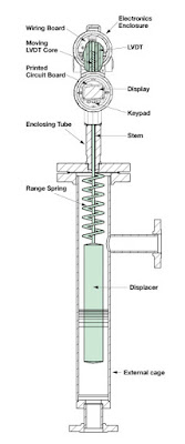
Displacer – A displacer is essentially a float and a spring that are characterized for a particular liquid and range of surface level movement. The displacer moves in response to liquid level, changing the location of a core connected to the displacer by a stem. The core is within a linear variable differential transformer. The electrical output of the transformer changes as the core moves.

Guided Wave Radar – A radar based technology that uses a waveguide extending into the liquid. The radar signal travels through the waveguide, basically a tube. The liquid surface level creates a dielectric condition that generates a reflection. Calculations and processing of the emitted and returned signals provide a measure of distance to the liquid surface. No moving parts.

Magnetostrictive – A method employing measurement of the transit time of an electric pulse along a wire extending down an enclosed tube oriented vertically in the media. A magnetic float on the exterior of the tube moves with the liquid surface. The float’s magnetic field produces the return signal to the sensor. Processing the time from emission to return provides a measure of distance to the liquid surface.

Pulse Burst Radar - A radar based technology employing emissions in precisely timed bursts. The emission is reflectex from the liquid surface and transit time from emission to return is used to determine distance to media surface.  Not adversely impacted by changes in media conductivity, density, pressure, temperature. No moving parts.

Frequency Modulated Continuous Wave Radar – Another radar based technology that employs a radar signal that sweeps linearly across a range of frequencies. Signal processing determines distance to media surface.  Not adversely impacted by changes in media conductivity, density, pressure, temperature. No moving parts.

RF Capacitance - As media rises and falls in the tank, the amount of capacitance developed between the sensing probe and the ground reference (usually the side metal sidewall) also rises and falls. This change in capacitance is converted into a proportional 4-20 mA output signal. Requires contact between the media and the sensor, as well as a good ground reference. No moving parts.

Ultrasonic Non-Contact – Ultrasonic emission from above the liquid is reflected off the surface. The transit time between emission and return are used to calculate the distance to the liquid surface. No contact with media and no moving parts.

Differential Pressure – Pressure sensor at the bottom of a vessel measures the pressure developed by the height of the liquid in the tank. No moving parts. A variation of this method is often called a bubbler, which essentially measures hydrostatic pressure exerted on  the gas in a tube extending into the contained liquid. It has the advantage of avoiding contact between the measuring instrument parts, with the exception of the dip tube, and the subject liquid.

Laser - Probably one of the latest arrivals on the liquid level measurement scene, laser emission and return detection is used with time interval measuring to accurately determine the distance from the sensor source to the liquid surface.

Load Cell - A load cell or strain gauge can be incorporated into the support structure of the liquid containing vessel. Changes in the liquid level in the vessel are detected as distortions to the structure and converted, using tank geometry and specific gravity of the liquid.

All of these technologies have their own set of attributes which may make them more suitable to a particular range of applications. Consulting with a product specialist will help determine which technologies are the best fit for your application.


Diaphragm Pressure Gauges for Industrial Process Measurement

diaphragm pressure gauge for industrial process measurement
Example of a diaphragm pressure gauge
Courtesy Wika
Diaphragm pressure gauges, like every device and instrument intended for use in industrial process measurement and control, have their own set of attributes making them an advantageous choice for some range of applications. Silvia Weber, product manager at Wika, a globally recognized leader in the field of pressure and temperature gauges, wrote an article for Process Worldwide (process-worldwide.com/) about diaphragm pressure gauges.

The article is included below and provides a comparison of the differences between Bourdon tube and diaphragm operating mechanisms, focusing on design and operational features of diaphragm pressure gauges and the range of application criteria for which they may be the best choice.

Pressure gauges are utilized in most operations where fluids are moved through a system. Gauges, though mechanical in operation, remain a mainstay of fluid operations because of their reliability, local display, ruggedness, and lack of reliance on electric power for operation. There are countless pressure gauge configurations to suit every application. Specifying the best gauge configuration for an application is accomplished by combining your process knowledge with the application expertise of a product specialist.


Protect Valuable Pressure Gauges and Transmitters With a Pressure Limiting Valve

pressure limiting valve for gauge or transmitter protection
Pressure limiting valve provides gauge
or transmitter protection from spikes
Courtesy Mid-West Instruments
Pressure gauges and transmitters, commonly found in fluid process control operations, are vulnerable to damage from transient spikes in system pressure that may range beyond the instrument's working range. These pressure spikes can impact instrument calibration, or even render the instrument or gauge inoperative. The cost of replacing gauges or transmitters is substantial enough to warrant the use of protective devices to prevent exposure to pressure spikes.

Mid-West Instruments manufactures a line of pressure limiting valves specifically intended for use with pressure gauges and transmitters. The Model 200 pressure limiting valve prevents instrument over-range and has an adjustable needle valve to dampen pulsation. The valve and be used with all types of instruments and pressure gauges, is suitable for mounting in any position, and is available in a range of materials for body and seals.

The document below provides more product detail, as well as installation and setup instructions. Providing a useful measure of protection for pressure gauges and transmitters is a simple operation. Reach out to product application specialists for help in formulating effective solutions.


Industrial Process Gauges - New Product Guide

industrial pressure gauge
One of the many pressure gauge versions
employed throughout industry
Courtesy Ametek - U.S. Gauge
Even with the large growth in the use of electronic measurement instruments throughout the process control sphere, mechanical gauges and indicators remain an important part of process measurement and control operations.

A broad line of industrial gauges and diaphragm seals is available from U.S. Gauge. The company has consolidated its offering into a product guide that provides simple and quick reference to the various product series.

For pressure:

  • Process Gauges
  • Liquid Filled Gauges
  • Test Gauges
  • General Equipment Gauges
  • Special Application Gauges

For temperature:

  • Adjustable Bimetallic Thermometers
  • Thermowells
  • Industrial Bimetallic Thermometers
  • Multi-Angle Industrial Thermometers
  • Digital Thermometers
  • Glass Tube Thermometers
The product guide also includes diaphragm seals and a range of electronic indicators, as well.

The guide illustrates gauges for every industrial application. Share your process measurement and control challenges with product application specialists, combining your process knowledge with their product application expertise to develop effective solutions.


Basic Guide to Understanding Pressure

absolute pressure transmitter for industrial process measurement control
One style of absolute pressure transmitter
Courtesy Yokogawa
The impact of pressure on industrial processes would be difficult to understate. Pressure is an element of process control that can affect performance and safety. Understanding pressure concepts and how to effectively measure pressure within a process are key to any operator's success.

Yokogawa, a globally recognized leader in process measurement and control, has made available a handbook on pressure that covers a range of useful topics. The content starts with the very basic concepts and moves quickly to practical subjects related to process measurement and control.

The handbook will prove useful to readers at all levels of expertise. Share your process measurement challenges with application specialists, combining your process knowledge with their product application expertise to develop effective solutions.


V-Cone® Flow Meter Conditions Flow For Accurate Measurement


Accurate measurement of fluid flow is a process requirement in many industrial operations. There are numerous methods employed in the measurement of fluid flow, of which the McCrometer V-Cone® is one entry with very particular advantages. Whether the application involves liquid, steam, or gas, this flow meter design, with its own flow conditioning built in, provides exceptional differential pressure flow measurements in a space saving format.

The video provides a clear illustration of how the V-Cone® design conditions fluid flow in order to provide better DP measurement performance. Share your flow measurement challenges with application specialists, combining your process expertise with their depth of product application knowledge to develop effective solutions.

Electronic Displacer Liquid Level Transmitter - How it Works, When to Use It

Displacer liquid level transmitter diagram
Electronic displacer liquid
level transmitter using spring
technology
Courtesy Magnetrol
An electronic displacer liquid level transmitter is intended for industrial applications requiring the continuous measurement of liquid level in a tank, vessel, or other containing space.

Magnetrol, a globally recognized leader in the design and production of level measurement instrumentation, describes the operating principle of their Digital E3 Modulevel® displacer level transmitter:
Electronic displacer level transmitter technology operates by detecting changes in buoyancy force caused by liquid level change. These forces act upon the spring supported displacer causing vertical motion of the core within a linear variable differential transformer.
The movement of the core within the LVDT generates an electrical signal which is further processed and serves as the output of the transmitter. The unit is designed to be externally mounted on a tank. Isolation valves are recommended.

The spring technology employed as a counterforce to the buoyancy of the displacer results in a stable signal that is not impacted greatly by vibration, agitation, or turbulence of the measured liquid.

The video below provides more detail, covering the features and advantages of this level measurement technology and the Magnetrol instrument. Share your level measurement challenges and requirements with a product application specialist. The combination of your process knowledge and their product application expertise will produce effective solutions.

Tank Blanketing Valve Function and Useful Features

tank blanketing valve
Tank Blanketing Valve
Caschco - Valve Concepts
The filling of vapor space in a liquid containing tank with a gas is referred to as "tank blanketing", and sometimes "padding". Specialized valves are available, designed to simplify the incorporation of a tank blanketing function in an operation.

Often, the gas employed to fill the vapor space in a tank is nitrogen. The purpose of blanketing can vary, but generally involves preservation of the stored product or safety. In both cases, one goal is to keep oxygen levels in the vapor space sufficiently low to inhibit ignition of flammable products, or minimize oxidation and its impact on stored product quality. The inflow of blanketing gas can also be used to keep the tank under positive pressure relative to the surrounding space, considered to harbor contaminants which could otherwise leak into the tank.


What are some functions of a tank blanketing valve?


  • Maintain positive pressure in the tank at a selected setpoint.
  • Provide gas control at very low flow rates, or close bubble tight, when tank liquid level is static.
  • Adjust gas flow to compensate for the maximum liquid draw down rate.
  • Provide sufficient closure to prevent supply gas from excessively pressurizing tank.
Blanketing valves are used in conjunction with vents to provide a full range of control over the pressure and content of the vapor space within a tank. A single valve solution eases the design and component selection burden of amassing individual components and combining them into a working assembly. Some useful features of a blanketing valve include:
  • Bubble tight shutoff to prevent wasting of purge gas.
  • Self cleaning flow path design.
  • Pressure balanced pilot, so supply pressure fluctuations do not impact the setpoint.
  • Setpoint not appreciably affected by changes in temperature.
  • Low maintenance requirements, including complete access to valve internals without removing the valve from the tank.
More detail, including a description of the elements required for proper valve sizing, is found in the document below. Share your fluid process measurement and control challenges with application specialists, combining your process experience and knowledge with their product application expertise to develop effective solutions.