Magnetic Level Indicators and Controls for Industrial Process Applications

Magnetic Level Indicators and Controls

Fluid process control operations frequently involve the storage of liquids in a vessel or tank. The continuous and accurate indication of the liquid level within the tank is an important data point for process control decision making and safety. Several tank level measurement methods and instrument types are available, each with its own set of characteristics that may be advantageous for a specific installation. 

A tank liquid level indicator's selection criteria often include: 

  • Does the process require direct or indirect measurement of level?
  • What level measurement accuracy and reliability is needed?
  • What is the tank shape, regular or irregular?
  • Are there concerns with media compatibility with measurement device materials of construction?
  • How often will maintenance or calibration be needed?
  • Is the instrument capable of operating at the process temperature and pressure for the application?
  • Does the application require local display and visibility or remote?
  • Are control signals from the level indication required? What type and transmission protocol?
  • What kind of redundancy and safety devices, such as additional switches, are needed?

Magnetically coupled liquid level indicators, or MLIs, are widely used in the process industry. They are accurate, consistent, and reliably indicate liquid level. These units are completely sealed and do not require any maintenance. MLIs also eliminate the vapor or liquid emission issues that plague sight and gauge glasses. 

Most Compelling Reasons for Using MLI's:

  • Level measurement is continuous. 
  • Operable without the use of electricity. 
  • Regardless of tank shape or profile, they provide a direct visual tank fluid level indication. 
  • They are available in wide operating temperature and pressure ranges. 
  • MLI construction is resistant to breakage.
  • A variety of materials are available to accommodate corrosive media. 
  • Externally mounted measuring indicators, switches, and transmitters do not come into contact with the process media. 
  • MLI's provide a continual operation that requires little maintenance. 
  • The level indication is viewable from a greater distance than glass sight gauges. 
  • With a single instrument, it is possible to measure large fluid level ranges.

Magnetic level indicators have a strong presence in tank liquid level measurement and should be considered a candidate for meeting those application requirements. There are numerous options for customizing the level indicator for each application.  Work with your local Sales Engineer,  a specialist in level measurement, about your application challenges and positive outcomes. 

For more information, contact your local Miller Energy, Inc. regional office:

South Plainfield, NJ Office
Serving Northern NJ, New York, and Fairfield County Connecticut
South Clinton Ave.
South Plainfield, NJ 07080
Phone: 908-755-6700
Toll Free: 800-631-5454
Fax: 908-755-0312

Exton, PA Office
Serving Southern NJ, Eastern PA, Delaware and Central and Eastern Maryland
505 Gordon Drive
Exton, PA 19341
Phone: 610-363-6200
Toll Free: 888-631-5454
Fax: 610-524-7254

Cleveland, OH Office
Serving Ohio
555 Golden Oak Parkway
Cleveland, OH 44146
Phone: 440-735-0100
Fax: 440-735-0123

Choosing the Right Industrial Level Technology In Foaming Situations

In the chemical, manufacturing, food and beverage, life sciences, and other process industries, foam is sometimes a problem in liquid tanks. There is no "one-size-fits-all" level measurement option for foam because of its fluid nature. Understanding the properties of the foam and the type of measurement required is critical. Foam can form in a tank for various causes, including injecting air or gas into the liquid or agitator/mixing blade activity. Understanding the nature of the foam and the process is essential to minimize potentially costly errors when choosing a level measurement technique, regardless of the source.

For more information about applying the right instrumentation for level measurement in the presence of foam, contact Miller Energy, Inc.

In New York Metro and Northern NJ
Phone: 800-631-5454

In Eastern Pennsylvania and Delaware:
Phone: 610-363-6200

https://millerenergy.com

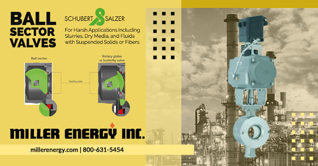
The Valve for Abrasive and Slurry On/Off and Control Applications: The Ball Sector Valve

Ball Sector Valve

The Ball Sector Valve is intended to perform well in harsh environments such as slurries, dry media, fluids containing suspended solids, or liquids containing fibers. When combined with pneumatic and electric actuators, it is the best choice for exact control in various process industries such as mining, pulp and paper, and the chemical industry. 

The ball sector valve comprises a hemispherical shell - the ball sector - that is securely held in place in the valve body by two large bearing stems.

Ball sector valves deliver exceptional performance in demanding applications. When conventional butterfly and ball segment valves are closed, their critical sealing components are subjected to the most wear in the valve. Because of the unique design of the ball sector, the seal seals through a surface part that is less prone to wear. The ball sector valve facilitates sealing through less exposed areas of the ball sector to avoid abrasion-caused leakage. The sealing surface is not exposed to high flow velocities significantly extends the service life of ball sector valves. A self-adjusting PTFE packing with an integrated spring element seals the shaft and protects the bearing from media particles. This innovative seal design, combined with a variety of materials and finishes for the ball sector and valve seat, significantly extends the valve's life compared to other valve technologies. As a result, it is particularly suited to abrasive, high viscosity, or fiber-containing media. 

The modified equal-percentage operating characteristic (difference pressure increases as the valve closes) combined with the outstanding rangeability of 300:1 means that the valve can be used for most control tasks. The valve body's special connection ensures that the differential pressure on the valve has little effect on the actuating torque. 

Other technologies, such as a segmented ball or rotary globe valves, employ an excentric shaft, causing the ball or plug to lift up from the valve seat when the valve begins to open. As a result, sealing areas are immediately subjected to permanent wear. Particulate can become lodged between the seal ring and the ball/plug. The ball sector valve has centric and robust trunnions that allow the ball sector to maintain constant contact with the valve seat, preventing media contamination. Changes in differential pressure have no effect on the permanent actuation torque.

For more information about Schubert & Salzer products, contact Miller Energy by calling 800-631-5454, or visit https://millerenergy.com.

Selecting Variable Area Flow Meters for Process Flow Measurement

Variable Area Flow Meters

Many industrial processes involve the movement of fluid product components, either liquid or gaseous, through pipes. Because processing is about control, an input to the facility's management, measurement, or data logging centers will answer the query, "How much is going through that pipe?" 

In the industrial process measurement and control industry, there are several ways for quantifying flow, each with unique characteristics that may be useful under certain operating situations. All flow measuring methods are indirect because the actual measurement is of a character influenced predictably by a change in the media flow. Flow measurement is a critical component that, when paired with other fluid properties, is used to calculate the total mass of a fluid passing through the measurement site. 

The variable area meter, commonly known as a rotameter and VA meter, is a tried and true flow measuring device that operates by creating an equilibrium between an upward force created by fluid motion and a downward force, gravity. A tapering glass or metal tube encases a specifically shaped float, also known as a shaped weight, in the device. VA meters must be positioned vertically, with the media flowing upward from the bottom, so that the gravity force required for functioning is correctly aligned with the flow direction. As fluid flows upward via the precisely tapered tube, drag is created on the float enclosed within the tube, pulling it upward. As the float rises, the open space between the float and the tube wall expands, causing the fluid velocity and drag force to decrease. The flow velocity within the tube will cause the weight to climb for any given flow volume until the drag force generated by the flow reaches equilibrium with the countervailing power of gravity on the float. The tube and float are well designed, allowing for an immediate indication of flow volume.

Variable area flowmeters have the following operating characteristics: 

  • There is no need for external power or fuel for functioning. 
  • Vertical installation is required, with flow arriving at the bottom. 
  • Meters are calibrated to a given chemical and temperature. 
  • The operation is stable and has a modest pressure drop. 
  • For operation, constant gravity is required. 
  • Flow rate can be read locally using a meter or a scale inscribed on the tube. 
  • The visibility of the float through the medium is required for unit flow readings using glass tubes. 
  • For industrial flow metering equipment, accuracy is relatively low. 
  • Inexpensive upkeep, simple construction, and low comparative cost.

Brooks Instrument, a world-renowned maker of flow, pressure, and level measurement equipment, created a brief paper highlighting the parameters to consider when specifying a VA meter and how each aspect influences the unit's performance. The description is realistic and straightforward to grasp. It is suggested reading for all process stakeholders who want to improve their flow measuring skills.

For more information about variable area flow meters contact Miller Energy. Call 800-631-5454 or visit https://millerenergy.com.

New Product Alert: The United Electric Controls Excela™ Electronic Switch

United Electric's Excela™ is the first switch of its type. Excela™ provides plant operators with an affordable way to upgrade to electronic performance. It has only two wires and is simple to place into the existing mechanical switch infrastructure. This unique, high-quality electronic pressure and temperature switch provide everything operators require for improved performance at an affordable price.

There are benefits and drawbacks to using advanced transmitters and old electromechanical switches at a facility. In terms of maintenance, an operator may spend at least ten times trying to maintain a switch over a transmitter. A transmitter, on the other hand, can be expensive and excessive for a modest application. There is a market void for economical, easy-to-install, drop-in-upgrade instrumentation for a facility's old mechanical switch infrastructure. To address the maintenance and upgrade cost concerns, the Excela™ was designed from the ground up to combine the benefits of the electromechanical switch (e.g., simplicity) and the transmitter (e.g., precision) at an inexpensive price point.

The Excela™ electronic switch is for plant upgrades by replacing mechanical switches with cutting-edge digital switch technology. It makes use of the existing mechanical switch wire as well as the attached discrete input power supply. In most cases, Excela™ is a direct drop-in replacement for existing mechanical pressure, differential pressure, and temperature instrumentation, making upgrading instrumentation within a plant cost-effective and straightforward. Typical uses are monitoring pressure and temperature for alarm and emergency shutdown in lubricating oil, boiler, furnace feed pumps, cooling, chiller water injection pumps, compressors, and many others.

For more information about the Excela™ electronic switch contact Miller Energy. Call 800-631-5454 or visit https://millerenergy.com.

Process Refractometers for Water Treatment Chemical Concentration Monitoring

Process Refractometers for Water Treatment


INTRODUCTION


Pure water treatment removes undesirable chemicals, biological contaminants, suspended solids, and gases from raw water. Water purification aims to produce water for a specific purpose, such as human consumption and medical or industrial use.


Polyaluminium coagulants are increasing use in potable water treatment plants, particularly for soft, colored surface waters. Polyaluminium chloride (PACl) is gradually replacing Alum (aluminum sulfate), a commonly used coagulant in water treatment plants. Alum coagulates at a limited pH range (between 5.5 and 6.5) and often requires alkali to the raw water to achieve the optimum coagulation pH. Furthermore, the alum floc produced is particularly fragile, which is vital if a coagulant is required to maximize color removal in a microfiltration-based water treatment process.


K-Patents Teflon Body Refractometer PR-23-M from Miller Energy, Inc.


APPLICATION


Water treatment by chemical precipitation is a complex process. It starts with adding flocculants, specifically, Polyaluminium Chloride (PACl) and Sodium Hydroxide (NaOH). PACl is a synthetic polymer dissolved in water. It precipitates in big volumetric flocs, which absorb suspended pollutants in the raw water. The turbidity of the raw water defines Polyaluminium Chloride quantity. PACl concentration must be higher than 10 % To keep the flocculation process smooth. Polyaluminium Chloride is stable in the storage tank; however, it tends to crystallize after some time. Vaisala K-PATENTS® refractometer monitors the concentration of PACl to inform about the need for tank or pipe cleaning, thus preventing blockage caused by the PACl crystals.


NaOH regulates pH level, increases alkalinity, and neutralizes acids in the water. In alkaline water, the coagulation and flocculation processes work more effectively. Moreover, sufficient alkalinity prevents dissolving the lead from pipes and pipe fittings and reduces the corrosive effect of the water to iron pipes.


Further, particles suspended in water start to precipitate and agglomerate to form larger particles, known as flocs. The flocs are then settled at the bottom, forming sludge, and then removed from the process. After separating most of the floc, the remaining suspended particles and unsettled floc get filtered to remove water.


In the filtration phase, the water goes through the layers of anthracite, sand, and gravel. As a result, organic compounds contributing to taste and odor get removed. Other remaining particles get trapped by adhering to the sand and gravel particles.


After harmful micro-organisms get removed through filtering, it is necessary to add disinfecting chemicals to the water to inactivate any remaining pathogens and potentially harmful micro-organisms. One of the disinfecting chemicals used is Sodium Hypochlorite (NaOCl). When dissolved in water, this chemical releases chlorine, which is an efficient and safe disinfectant if added in a sufficient amount. Apart from sodium hypochlorite, liquid chlorine and chlorine dioxide are also choices as disinfectants.


Fluoride may also be added to the water to reduce tooth decay and prevent chronic diseases. However, fluoride in the water must not exceed recommended levels. Excessive levels of fluoride can be toxic or cause undesirable cosmetic effects such as staining of teeth.


Sodium Hypochlorite is unstable and quickly decomposes. The stability of NaOCl solution is dependent on the following factors:


  • Hypochlorite concentration
  • The temperature of the solution
  • PH value of the solution
  • The concentration of the impurities during catalyzing decomposition
  • Exposure to light


With the process refractometer, it is possible to monitor NaOCl concentration and control the disinfection conditions.


The water purification disinfection stage happens in the disinfectant basin. Then, corrosion control assures the high quality of the purified water. Finally, the pure water gets stored for further consumption.


INSTRUMENTATION AND INSTALLATION


Vaisala K-PATENTS® Teflon Body Refractometer PR-23-M provides in-line measurements of Polyaluminium Chloride and Sodium Hydroxide at the initial stage of purification, ensuring the efficient flocculation of undesired particles. In addition, through the measurement of Sodium Hypochlorite and Fluoride at the water disinfection stage, high-quality purified water at the outlet is assured.


Refractometer installations happen in three different points in a by-pass loop between each chemical tank pump outlet and the treatment point. The refractometer allows monitoring the chemicals concentration at the exit from the storage tank to the pipe treatment point.


Typical measurement ranges are:

  • PACl is ca. 10-11 %
  • NaOH is ca. 40-45 %
  • NaOCl is ca. 8-12 %

Miller Energy, Inc.
https://millerenergy.com
800-631-5454