Understanding the Operation of Mass Flow Controllers (MFCs)

The basic construction of mass flow controllers (MFCs) consists of four main components. A body, a thermal sensor, a printed circuit board, and a magnetic control valve. As gas enters the flow body, a laminar flow element or restrictor diverts a precise portion of the gas to pass through the thermal sensor. The thermal sensor is the heart of the mass flow controller and consists of a bypass tube fitted with a heater element and two temperature sensors. As gas enters the sensor bypass tube, the upstream and downstream temperature sensors measure the temperature differential between gas entering the bypass tube and exiting it. 

When choosing an MFC supplier, consider whether the manufacturer provides zero stability specifications, also known as sensor stability, which indicates the device's ability to maintain accuracy over time. Good sensor stability ensures the MFC delivers highly accurate and consistent results with less frequent recalibration or replacements needed. A stable, precise sensor guarantees regular, precise process control. As the thermal sensor measures the change in the flow temperature,  it sends a signal to the circuit board, which interprets the data into flow output and compares it to the setpoint received from the user setpoint signal. If the setpoint, or required value, is higher than the measured value or flow output, the controller will open the control valve, letting more flow through. Suppose the setpoint is lower than the flow output. In that case, the control valve will close, decreasing flow, caused when a coil inside the magnetic control valve sends an electrical current around a valve stem, which moves the valve plunger by thousands of an inch. The circuit board is the device's brain, so pay close attention to the electronics and firmware architecture when evaluating an MFC. The MFC should have the ability to support advanced alarms and diagnostics to monitor and correct issues before the overall process is negatively affected. Check to see what built-in alarms and diagnostics are available. 

Brooks Instrument devices support flow output and additional alerts like flow totalization, valve drive, flow obstruction, and calibration. All Brooks devices are tested as complete systems to ensure robust and accurate operation and maintain calibration to international standards. 

In Pennsylvania and Ohio, contact Miller Energy to learn which Brooks Instrument solution is right for your process.

In Eastern Pennsylvania:
Phone: 610-363-6200

In Western Pennsylvania:
Phone: 412-257-0200

In Ohio:
Phone: 440-735-0100

https://millerenergy.com

Critical Ethylene Level and Flow Application Brochure

Critical Ethylene Level and Flow Applications

In ethylene plants, balancing environment, health, and safety is essential while maximizing productivity.

Level and flow instrumentation will assist in preventing loss of primary containment and maintaining a safe environment inside of the tank. That’s critical, because incident consequences are significant, with the direct cost of a work-related death of $1M and indirect costs approximately 4 times greater. In addition, there is the lasting damage to your brand reputation and the compromised safety of the local community. Instrumentation can also assist in maximizing productivity, including interface type measurement in some of the harshest environments.

This brochure contains a wide spectrum of Magnetrol® and Orion Instruments® level and flow products that conform to the latest safety standards, including SIL requirements, to assist in the most critical applications in ethylene plants.


For more information about Magnetrol and Orion Instruments products contact Miller Energy, Inc. Call them at 800-631-5454 or visit their website at https://millerenergy.com.

Sliding Gate Control Valves from Schubert & Salzer


Schubert & Salzer's sliding gate control valves are designed as an effective alternative to traditional control valves. The sliding gate valve controls liquid, vapor, and gaseous media precisely, quickly, and economically. The design is uniquely simple, but is intelligently built to handle complex applications that require precise control under taxing conditions. They are an excellent choice for a variety of media, including steam, liquids, and gases.

Sliding Gate Control Valve Operation

A sealing plate with many crossways slots of equal height is fixed in the body at right angles to the flow direction. A moving disc with the same slot arrangement moves in parallel to the fixed disc, thereby changing the flow cross-section. The prevailing differential pressure presses the moving disc against the fixed disc and seals it. 

The machined orifices in the fixed plate or disc can vary in design, size, and configuration, determining the flow coefficient (Cv) and the flow characteristic of the valve. As the cross sectional area changes and the valve modulates, flow is broken apart, creating a variable field of area flow, which reduces energy and noise. The differential pressure creates a unique seal between the two plates, and when in the sealed position, an overlap of approximately 1 mm creates a leak-tight valve.

ADVANTAGES OF THE SLIDING GATE CONTROL VALVE

  • Fits into tight spaces
  • Outstanding rangeability
  • 40:1 to 160:1
  • Easy to install and maintain
  • Variable Cv Values
  • Significantly reduced energy consumption
  • Minimal wear
  • Extremely low leakage rate
  • Optimal flow control
  • Maximum differential pressures

For more information about Schubert & Salzer products contact Miller Energy, Inc. Call them at 800-631-5454 or visit their website at https://millerenergy.com.

The Vaisala K-PATENTS PR-43A Sanitary Process Refractometers for Food, Beverage & Dairy Industries

Vaisala K-PATENTS® Sanitary Process Refractometers PR-43-AC for hygienic installations in small pipe line sizes of 2.5 inch and smaller; PR-43-AP for hygienic installations in large pipes, tanks, cookers, crystallizers and kettles and for higher temperatures up to 150°C (300 °F); and the PR-43-APT for flush mounting installations in cookers, cooling crystallizers and other vessels that have scrapers or mixers.

Sanitary Refractometer Applications:

Extraction, evaporation, brewing, distilling, sugar dissolving, blending, filling. Alcohol, rum, whiskey, brandy, vodka, molasses, liquors, cider, alcoholic beverages, pre-mixed liquors. Beer and malt beverages, wort, cut beer, root beer. Juices, blended vegetable and fruit juices and nectars, still drinks, vegetable and juice concentrates, iced tea and coffee, instant coffee and tea. Soft drinks, energy and sport drinks, beverage base. Wines, grape must.

Sanitary Refractometer 3A Approval:

The Sanitary refractometer PR-43-A is Sanitary 3-A approved to meet the highest hygiene requirements of food production. The 3-A Symbol assures that the Sanitary Refractometer

PR-43-A conforms to 3-A Sanitary Standard Number 46-04 for Refractometers and Energy-Absorbing Optical Sensors for Milk and Milk Products and it has passed the independent Third Party Verification inspection for 3-A Symbol authorization.

For more information about Vaisala K-PATENTS products in Metro New York, New Jersey, Pennsylvania, Delaware, and Northern Ohio contact Miller Energy, Inc. Call them at 800-631-5454 or visit their web site at https://millerenergy.com.

Crane Duo-Chek® Valves from Miller Energy, Inc.

Crane Duo-Chek® high performance non-slam check valves are available in the sizes, pressure classes and configurations required to meet the most demanding of applications. 

The Crane Duo-Chek® wafer valve design is generally stronger, lighter, smaller, more efficient, and less expensive than conventional swing check valves. Its design meets API 594, width is approximately one fourth the face to face dimension and is 15% to 20% the total weight, on most popular sizes, making them less expensive than a swing check valve. It is much easier to install between standard gaskets and line flanges. The savings compound during installation due to ease in handling and only one set of flange studs is required. Therefore, it is more cost-effective to install, and also to maintain.

For more information about Duo-Chek®  valves, contact Miller Energy, Inc. Call 800-631-5454 or visit  https://millerenergy.com.


Liquid Interface Level Measurement Using Guided Wave Radar, Magnetic Level Gauges, Float & Displacer, Thermal Dispersion, and RF Capacitance

Liquid Interface Level Measurement

The need for interface measurement arises whenever immiscible liquids - those incapable of mixing - reside within the same vessel. The lighter material rises to the top and the heavier material settles at the bottom. In oil production, for example, water or steam is used to extract oil from a well. Well fluids then route to production separators where they settle into their primary constituent parts as a water-hydrocarbon interface. Water may also be used as a transport medium or a cleaning agent and forms an interface with an allied material which is later extracted.

Knowing the position of a process interface is necessary for maintaining product quality and operations efficiency. The interface is measured and controlled by precision level switches and transmitters. Though at least 20 different types of liquid level measurement devices are in service today, only a very few are suitable for accurate and reliable interface measurement. Grouped by their operating technologies, these include Buoyancy (Floats and Displacers), RF Capacitance, Thermal Dispersion, Radar, and Redundant Technologies (those combining two measurement technologies in one instrument).

Interface Level Measurement
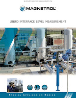
The five leading interface measurement technologies in use today are Guided Wave Radar, Magnetic Level Gauges, Float & Displacer, Thermal Dispersion, and RF Capacitance. These five leading interface measurement technologies in use today are discussed in the technical bulletin titled "Liquid Interface Level Measurement" and produced by Magnetrol International.


For more information on any industrial level control application, contact Miller Energy. Call them at 800-631-5454 or visit their website at https://millerenergy.com.