Process Automation: Valve Actuator Limit Switches

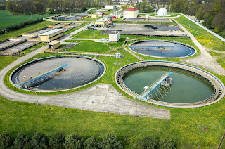
municipal water treatment plant
Municipal water treatment plant
Limit switches are devices which respond to the occurrence of a process condition by changing their contact state. In the industrial control field, their applications and product variations are almost countless. Essentially, the purpose of a limit switch is to serve as a trigger, indicating that some design condition has been achieved. The device provides only an indication of the transition from one condition to another, with no additional information. For example, a limit switch triggered by the opening of a window can only deliver an indication that the window is open, not the degree to which it is open. Most often, the device will have an actuator that is positively activated only by the design condition and mechanically linked to a set of electrical contacts. It is uncommon, but not unknown, for limit switches to be electronic. Some are magnetically actuated, though most are electromechanical. This article will focus on limit switch designs and variants used in the control and actuation of industrial process valves.
Employed in a wide range of industrial applications and operating conditions, limit switches are known for their ease of installation, simple design, ruggedness, and reliability.
Valves, devices used for controlling flow, are motion based. The movable portions of valve trim create some degree of obstruction to media flow, providing regulation of the passage of the media through the valve. It is the movement of critical valve trim elements that limit switches are used to indicate or control. The movable valve trim elements commonly connect to a shaft or other linkage extending to the exterior of the valve body. Mounting electric, hydraulic, or pneumatic actuators to the shaft or linkage provides the operator a means to drive the mechanical connection, changing the orientation or position of the valve trim and regulating the media flow. Because of its positive connection to the valve trim, the position of the shaft or linkage is analogous to the trim position and can be used to indicate what is commonly referred to as “valve position”. Limit switches are easily applied to the valve shaft or linkage in a manner that can provide information or direct functional response to certain changes in valve position.
In industrial valve terms, a limit switch is a device containing one or more magnetic or electrical switches, operated by the rotational or linear movement of the valve.
What are basic informational elements that can be relayed to the control system by limit switches? Operators of an industrial process, for reasons of efficiency, safety, or coordination with other process steps, may need answers to the following basic questions about a process control valve:
  • Is the valve open?
  • Is the valve closed?
  • Is the valve opening position greater than “X”?
  • Has the valve actuator properly positioned the valve at or beyond a certain position?
  • Has the valve actuator driven the valve mechanism beyond its normal travel limits?
  • Is the actuator functioning or failing?
Partial or complete answers to these and other questions, in the form of electrical signals relayed by the limit switch, can serve as confirmation that a control system command has been executed. Such a confirmation signal can be used to trigger the start of the next action in a sequence of process steps or any of countless other useful monitoring and control operations.

Applying limit switches to industrial valve applications should include consideration of:
  • Information Points – Determine what indications are necessary or useful for the effective control and monitoring of valve operation. What, as an actual or virtual operator, do you want to know about the real time operational status of a valve that is remotely located. Schedule the information points in operational terms, not electrical switch terms.
  • Contacts – Plan and layout a schedule of logical switches that will provide the information the operator needs. You may not need a separate switch for each information point. In some cases, it may be possible to derive needed information by using logical combinations of switches utilized for other discrete functions.
  • Environment – Accommodate the local conditions and hazards where the switch is installed with a properly rated enclosure.
  • Signal – The switch rating for current and voltage must meet or exceed those of the signal being transmitted.
  • Duty Cycle – The cycling frequency must be considered when specifying the type of switch employed. Every switch design has a limited cycle life. Make sure your selection matches the intended operating frequency for the process.
  • Auxiliary Outputs – These are additional contact sets that share the actuation of the primary switch. They are used to transmit additional signals with specifications differing from the primary signal.
  • Other Actuator Accessories – Limit switches are often integrated into an accessory unit with other actuator accessories, most of which are related to valve position. A visual local indication of valve position is a common example.
Switches and indicators of valve position can usually be provided as part of a complete valve actuation package, provided by the valve manufacturer or a third party. It is recommended that spare contacts be put in place for future use, as incorporating additional contacts as part of the original actuation package incurs comparatively little additional cost.

Employing a properly configured valve automation package, with limit switches delivering valve status or position information to your control system, can yield operational and safety benefits for the life of the unit. Good advice is to consult with a valve automation specialist for effective recommendations on configuring your valve automation accessories to maximize the level of information and control.

Succeeding: Engineer as Peacemaker

Miller Energy engineer
Make Allies, Not Adversaries

Let's take a step away from the technical, but still focus on an important aspect of our work.

As engineers involved in process measurement and control, we are accustomed to everybody else looking to us for answers and solutions. We are the people that make things work. Occasionally the pressure and stress can get a little intense and strip away some of our civility in our dealings with those around us. You may have bitter experience with this as either victim or perpetrator. It never ends well. With a private and candid self-assessment about how we view and interact with other stakeholders in our projects, we may be able to scale down some of our stress and better focus on the reality of the task at hand. Consider the points below. Comment and add a few points of your own.

You are an expert, but so are they.


Accept that, just as you have specialized knowledge that others do not, they have specialized knowledge or insight you may lack. Encourage the sharing of knowledge with those you interface with on a project. Try to be proactive and ask gently probing questions to ascertain the comprehension level of others involved in the project in various roles. Their increased understanding of key project technical concepts will promote more effective communication throughout the duration of the project. It can also help to avoid missteps in your own progress. Good people appreciate the time you take to provide basic explanation of concepts they may not fully understand, but need to know. Make valuable allies of the other project stakeholders by freely contributing your expertise. It is an investment that costs you little, but may pay immense dividends at some future time.

Everybody else's job usually looks easier than it really is.


All jobs have their own special challenges and responsibilities that generate stress. Accept the notion that you probably do not fully comprehend the burdens on those around you. Your portion of the project is certainly critical, but no more so than that of anybody else. Everybody needs to perform or nobody succeeds. Try not to view your project tasks as compartmentalized, but rather as part of the combined joint effort of all stakeholders. Help out others whenever you can. Again, make allies.  

Everybody is somebody's customer.


Whomever you deliver your work product to is your customer. The people delivering their work to you should view you as their customer. Make your customers happy by adjusting aspects of your procedures to better satisfy their needs. In a more technical sense, your modified process output becomes an improved input to their process. Small changes in your delivery may produce comparatively large returns in customer satisfaction. Allies.

Do not embarrass or demean others...especially in public settings.


Embarrassment breeds anger, a desire for revenge, and other bad and unproductive things. Avoid words and deeds that will make a coworker or stakeholder look bad in front of others. If there is a problem, if there is a mistake, try to deal with it discreetly whenever possible. Giving a someone a chance to repair a mistake before it becomes public builds value in your relationship. Certainly, there can be instances where more is at stake than someone's pride. Use good judgement to recognize when you can privately give someone an opportunity to amend a situation without causing harm.

Reach a common understanding of project scope and technical details


Your organization's management or your company's client, whatever the case may be, will likely have project expectations which will be clearly understood in their mind, but perhaps not fully described to all those tasked with specific performance. It is also possible, even probable, these same stakeholders will have misconceptions or a lack of technical knowledge about certain facets of the project. Omissions from the project specs and gaps in the common understanding of technical aspects related to the work requirements can easily turn a fairly straight forward task into a wildfire of organizational mayhem. The way in which these situations are handled must be diplomatic. Injured egos can do more damage to project harmony and progress than the facts ever will. The delivery method for the facts will likely be more crucial than the facts themselves.

It's not about being right. It's about being successful.


At our company we recognize customers are more than merely people that buy things from us. They are people to whom we contribute our time and talent to help achieve their success,... which inevitably will lead to ours. Never hesitate to let us know how we are doing, or how we can help.

Industrial Control Systems Present Unique Cybersecurity Challenges

industrial control system cybersecurity
Industrial control systems have unique
cybersecurity challenges.
The International Society of Automation is offering a free white paper entitled “What Executives Need to Know About Industrial Control Systems Cybersecurity”. The article provides useful commentary and information that establishes the scope of cybersecurity in the industrial process control space and provides a basic framework for understanding how every process may be impacted by lax cybersecurity efforts. The author, Joseph Weiss, differentiates Industrial Control System (ICS) cybersecurity from that of organizational IT through a review of various attributes common to both types, including message confidentiality, integrity, time criticality, and more. Any reader’s awareness and understanding of the cybersecurity risks to their operation will be enhanced through this article. I finished reading the article wanting more on the subject, and ISA is certainly a resource for additional content.

A quote from the article...
“Cyber incidents have been defined by the US National Institute of Standards and Technology (NIST) as occurrences that jeopardize the confidentiality, integrity, or availability (CIA) of an information system.”
ICS cybersecurity extends beyond preventing malicious outside intruders from gaining access. It is an important part of maintaining the overall operating integrity of industrial processes. A holistic approach is advocated to identify physical risk factors to the process and its componentry (previous article on device protection), as well as vulnerabilities that may prevent exploitation by unauthorized parties. Weiss goes on to describe the role and qualifications of the ICS Cybersecurity Expert, essentially an individual that can function effectively as an IT cybersecurity tech with the added skills of an industrial control systems expert.

A synopsis of attack events is provided in the article, with the author’s conclusion that not enough is being done to secure industrial control systems and the risk exposure is substantial in terms of potential threats to personnel, environment, and economy. By providing your name and email address, you can obtain the white paper from the ISA website. Your time spent obtaining and reading the article will be well spent.

For any specific information or recommendations regarding our products and cybersecurity, do not hesitate to contact us directly. We welcome any opportunity to help our customers meet their process control challenges.


Cavitation - Scourge of Industrial Process Control Valves Everywhere

Cavitation produces vapor bubbles in liquids
Cavitation produces bubbles in flowing process liquids
Consider a generic industrial fluid process control operation. There are pumps, valves, and other components installed in the process lines that, due to their interior shape or their function, cause changes in the fluid motion. Let's look specifically at control valves and how their throttling operation can create conditions able to greatly impact the valve itself, as well as the overall process.

Fluid traversing a control valve can undergo an increase in velocity when passing the constriction presented by the valve trim. Exiting the trim, fluid then enters the widening area of the valve body immediately downstream with a decrease in velocity. This change in velocity corresponds to a change in the kinetic energy of the fluid molecules. In order that energy be conserved in a moving fluid stream, any increase in kinetic energy due to increased velocity will be accompanied by a complementary decrease in potential energy, usually in the form of fluid pressure. This means the fluid pressure will fall at the point of maximum constriction in the valve (the vena contracta, at the point where the trim throttles the flow) and rise again (or recover) downstream of the trim.

This is where cavitation begins.

If the fluid being throttled is a liquid, and the pressure at the vena contracta is less than the vapor pressure of the liquid at the flowing temperature, portions of the liquid will spontaneously vaporize. This is the phenomenon of flashing. If, subsequently, the pressure of the fluid recovers to a level greater than the vapor pressure of the liquid, any flashed vapor will rapidly condense, returning to liquid. This collapse of entrained vapor is called cavitation.

Flashing, the generation of vapor bubbles within the liquid, will precede and set the stage for cavitation. When the flashed vapor bubbles condense to liquid they often do so asymmetrically, with one side of the bubble collapsing before the rest of the bubble. This has the effect of translating the kinetic energy of the bubble’s collapse into a high-speed “jet” of liquid in the direction of the asymmetrical collapse. These liquid “microjets” have been experimentally measured at speeds up to 100 meters per second (over 320 feet per second). What is more, the pressure applied to the surface of control valve components in the path of these microjets can be intense. An individual microjet can impact the valve interior surfaces in a very focused manner, delivering a theoretical pressure pulse of up to 1500 newtons per square millimeter (1.5 giga-pascals, or about 220000 PSI) in water. In an operating fluid system, this process can be continuous, and is known to be a significant cause of erosive wear on metallic surfaces in process piping, valves, pumps and instruments. As the rapid change in pressure takes place, the bubbles (voids in the liquid) collapse (implode), and the surrounding metal surfaces are repeatedly stressed by these implosions and their subsequent shock waves.

Consequences for control valves, as well as for the entire control process, vary and are often destructive. They may include:
  • Loud noise
  • Strong vibrations in the affected sections of the fluid system
  • Choked flow caused by vapor formation
  • Change of fluid properties
  • Erosion of valve components
  • Premature destruction or failure of the control valve 
  • Plant shutdown
The video provides a visual demonstration, through clear piping, of what happens inside the piping system when a valve is operated in a manner that causes substantial cavitation.

The solution lies in minimizing the potential for cavitation to occur through proper valve selection and sizing, along with coordinating operating characteristics of pressure drop inducing components with the total system performance. One valve manufacturer's recommendations are summed up in four basic approaches.
  • Avoidance of cavitation through proper valve selection. Use a valve with a rated liquid pressure recovery factor greater than that required for the application. Some applications may be suitable for the use of an orifice plate downstream of the valve.
  • Cavitation Tolerant Components capable of withstanding limited amounts of cavitation without excessive wear. Increased flow noise is likely to accompany this route.
  • Prevention of cavitation through the use of valve trim design that reduces pressure in several steps, avoiding excessive flashing. These valves can be expensive, but their effectiveness makes them an alternative worth considering.
  • Containment of the harmful effects of limited to moderate cavitation through trim designs that eliminate contact of the fluid with metal surfaces which are more susceptible to damage.
Share your requirements and application challenges with a valve specialist and gain insight through their recommendations. Combining your process knowledge with their product application expertise will yield a great solution.


New Level Transmitter From Orion Instruments

Orion magnetostrictive level transmitter
Direct insertion and external mount versions of
Orion JM4 Magnetostrictive Level Transmitter
Courtesy Orion Instruments
Orion Instruments, a world class manufacturer of magnetic level indicators, level switches, and level transmitters, has released a new product for use in the industrial process measurement and control field. Their Jupiter Model JM4 magnetostrictive transmitter incorporates the company's many years of research, development, and field experience to provide a safer, simpler, and smarter transmitter for liquid level measurement and control.

The new model from Orion boasts level measurements with accuracy as high is +/-0.05" (1.27mm). The transmitter head can be rotated up to 310 degrees with an option for remote mounting. Variants are available for direct insertion or external mounting, with approvals for a number of area classifications. There are other valuable features to this series of level measurement instruments that reflect Orion's expertise in the field.

Browse the new product brochure included below. It provides illustrations of the product and its operating principle, along with dimensioned drawings and a listing of all the product options and variants. You can always obtain whatever information you need about Orion level measurement instruments from a product specialist. Share your liquid level measurement challenges and requirements with them for recommendations on the best solutions.


Coriolis Mass Flow Meter - Operating Principle, Applications, Advantages

Coriolis flow meter by Yokogawa
Coriolis Flow Meter - Courtesy Yokogawa
Coriolis mass flow meters are widely used throughout the process measurement and control field. Their basic operating principle, combined with modern sensor and signal processing technology, provide a list of positive aspects.

Directly measure mass flow rate based on the principle of measurement.

Measure the mass flow rate with high accuracy of ±0.1%.

Provide a wide usable measurement range.

Deliver density measurement based on oscillating frequency.

Not materially impacted by fluid viscosity or density.

Coriolis flowmeters also do not need straight pipe sections upstream or downstream of the flowmeter. They also have the ability to measure non-conductive fluids. 

I have included an interesting video, produced by Yokogawa, a world class manufacturer of industrial process measurement and control instrumentation. It provides a clear and insightful illustration of the Coriolis principle and how it is used to provide accurate mass flow measurement.

Share your process measurement and control challenges with an instrumentation specialist. Combining your detailed process knowledge and their product application expertise will yield positive solutions.


Miller Energy Expanding Customer Connectivity With New Website Function

Engineering technician inspecting precision part
At Miller Energy, use website chat to connect directly with technicians
and product specialists.
Miller Energy will be rolling out real time chat on their website in early February. This new feature is another in a long line of continuous improvements the company has brought on line to better serve and connect with their customer base. On the desktop version, a chat widget will appear on every website page as a small tab on side of the display. A click of the widget will open a chat window and the visitor can type in their question or comment. Site visitors using mobile devices are afforded the same functionality.

Steve Collins, the Miller Energy website designer at CMS4i, commented on MEI's increased level of connectivity..
"The chat implementation at Miller Energy is notable because it connects customers directly with technically qualified employees that are part of the day to day company operations. Customers will be communicating with real “hands on” engineers and specialists familiar with process measurement and control, and engaged in the field on a daily basis."
Look for the chat function on the Miller Energy website in early February. Use it to get fast answers to your questions from knowledgeable and engaged industry professionals.