Bimetal Thermometers for Industrial Process Measurement

stainless steel bimetal thermometer
Bimetal thermometers have a place in modern process
measurement systems.
Image courtesy Wika
Temperature measurement is everywhere, with broad ranges of accuracy, range and other operational requirements to bring the measurement data into a process management or control system. The process could be as simple as measuring a cooking temperature, or a part of a complex refining operation. Temperature provides an indication of heat energy level that is used in many ways throughout process control.

Though there are many instruments and technologies available to measure temperature, one that everyone is familiar with is the dial thermometer. A familiar numeric scale and a pointer indicate the temperature at the sensing location. Even within the product range of dial thermometers, there are several differing methods utilized to produce a temperature reading. One of these is the bimetal thermometer.

A bimetallic thermometer is named for the mechanism that responds to process temperature and provides the force to position the indicator needle over the scale on the dial face. A bimetal is formed from two dissimilar metals bonded together. The metals expand and contract at different rates in response to a change in their temperature. A bimetal thermometer relies on the predictable deformation of a bimetal spring or strip in response to a temperature change. The mechanical deformation is transformed into rotational movement of the indicating needle on the instrument face where the corresponding temperature can be read by a technician or operator. This design principle has been in use throughout laboratories, kitchens, and industry for many years and has proven to be predictably accurate, stable, and rugged.

The major advantages of the bimetallic thermometer are its relative cost, ease of use, and ability to function without any external power source. This class of instruments provides operability up to +1000°F.

When applying dial faced thermometers, there are several main considerations.

  • Scale - The display behind the indicating pointer. The scale divisions impact the instrument's accuracy at indicating process temperature.  
  • Range - The physical suitability of the instrument to be exposed to the temperatures which may be present in the process. May be the same as scale.
  • Dial Size - Larger diameter dial faces make reading the instrument indications easier.
  • Connection - There are numerous options for the way in which the probe or stem, which is inserted into the process, attaches to the dial portion or head of the instrument. Common arrangements are back, side, or bottom connected. If the head cannot be rotated or angled, the connection attributes may be the sole determinant of how the dial face is oriented.
  • Stem Length - The stem extends from the head into the process. Coordinating the stem length with the insertion depth into the process and the placement of the instrument is important to achieving a useful and ergonomic installation.
  • Materials of Construction - Make sure the selected instrument is rugged enough to withstand expected environmental conditions at the installation site.
These are only the primary considerations. Share your operational requirements with a product specialist. Leverage your own knowledge and experience with their product application expertise to develop the optimal solution.
Guided Wave Radar - An Option for Level Measurement in Hygienic Applications

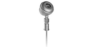
GUIDED WAVE RADAR LEVEL TRANSMITTER FOR HYGIENIC APPLICATIONS
A special version of the Magnetrol Eclipse 705
is configured for hygienic applications.
Image courtesy Magnetrol
Measurements of a variety of process conditions are utilized to monitor and control operations and output. One general goal of measurement, other than answering the question "how much", is to avoid or minimize any interference with the process itself. A second goal is to not be fooled by the process into returning a false measurement result.

Guided wave radar is based upon the principle of TDR (time domain reflectometry). Pulses of electromagnetic energy travel from the emitting antenna via a fixed waveguide or probe immersed in the target medium. When it contacts the media surface, the pulse energy is reflected back along the probe to a receiving antenna. The instrument actually measures the time elapsed between the pulse transmission and the detection of the reflected return. The time measurement is used to calculate the distance from the antenna to the media surface. The distance calculation, with knowledge of the vessel, can be converted into a value indicating media level or volume. Of course, this is a simplified account of the operating principal.

Guided wave radar (GWR), as opposed to an open style radar level measurement method, uses a probe immersed in the process media to guide high-frequency electromagnetic waves into the media being measured. While it does involve contact by the sensing instrument with the media, GWR eliminates interference from fixtures or structures that may exist within the tank or vessel. The immersion probe waveguide also attenuates the impact of media turbulence and other potential disturbances. The waveguide reduces the potential impact of elements that may adversely impact the measurement accuracy, resulting in greater accuracy and reliability of the measurements.

For hygienic applications, the transmitters are available with 304 stainless steel housings designed specifically for use in facilities with the special requirements for the wetted and non-wetted materials, process connections and surface finishes of hygienic industries. In addition to high accuracy, the GWR instrument output is not impacted by media buildup on the sensing probe.

Share your level measurement challenges with process instrumentation specialists. Leverage your own process knowledge and experience with their product application expertise to develop an effective solution.


Register Early for the Yokogawa Users Conference 2018

Yokogawa Users Conference North America
The Yokogawa Users Conference for North America will be held
on September 10 - 13 in Orlando, FL
Yokogawa is hosting its Users Conference in Orlando FL for 2018. This excellent event enables attendees to:

  • Learn how to maximize the value of their measurement and control investment.
  • View and learn about the latest products and solutions for process measurement and control.
  • Interact with subject experts and Yokogawa partners.
  • Network with industry peers.
  • Build knowledge of best practices for particular industries and measurement and control in general.
There will be panel discussions, technical sessions, exhibits and more. The event is scheduled for September 10th through 13th, and early registration has started. Make plans to attend and build your knowledge base. You can find the registration information at the conference website, or reach out to a Yokogawa representative to find out more.

Magnetic Flow Meters

magnetic flowmeter flow meter on large flanged lined pipe section
Magnetic flow meters can be easily applied in lined
pipe sections and those of substantial diameter.
Image courtesy Yokogawa
The measurement of fluid flow is a common process control function. Flow measurement can have a range of differing output requirements, depending upon the needs of the process operators. With many technologies and instruments from which to choose, knowledge of the principals behind each measurement technology and basic operation requirements can help in the selection of the best instrument for each application. 

Anywhere there are pipes, somebody wants to know how much fluid is passing through them. Industrial flow meters rely on their ability to measure the change in some physical characteristic of fluid moving within a pipe that can be related to fluid velocity or mass flow. Depending upon the nature of the raw measurement, additional information and processing may be necessary to convert the base measurement into a useful measurement of flow rate.

In the processing industries, differing technologies are used to measure fluid motion. Some common technologies include magnetic, ultrasonic, vortex shedding, Coriolis and differential pressure. This list is not exhaustive, and several other technologies will certainly be found in use. Each methodology survives within a competitive marketplace due to its unique combination of performance and value attributes. Let's look at magnetic flow meters, also referred to as magmeters.

The operational principle of a magnetic flow meter is based upon Faraday’s Law. This fundamental scientific principle states that a voltage will be induced across a conductor moving at a right angle through a magnetic field, with the voltage being proportional to the velocity of the conductor. The principle allows for an inherently hard-to-measure aspect of a conductive fluid to be expressed via the magmeter. In a magmeter application, the instrument produces the magnetic field referred to in Faraday’s Law. The conductor, moving at a right angle to the magnetic field, is the fluid. The actual measurement of a magnetic flow meter is the induced voltage corresponding to fluid velocity. This can be used to determine volumetric flow and mass flow when combined with values of other fluid properties and the pipe cross sectional area. Magnetic flow meters enjoy some positive application attributes.
  • Magnetic flow meters have no moving parts.
  • The instrument, which often resembles a pipe section, can be lined with corrosion resistant material for use with aggressive media.
  • With no sensor insertions or obstructions in the fluid path, the impact of the instrument on the flow is minimal.
  • Accuracy, when compared to other technologies, is high.
  • Application to laminar, turbulent, and transitional flow profiles is permissible.
  • Generally, measurement is not adversely impacted by fluid viscosity, specific gravity, temperature and pressure.
  • Magnetic flow meter technology can be applied to a very wide range of pipe sizes.
  • Device responds rapidly to changes in fluid flow.
  • Can be successfully applied to liquids containing heavy particulates.
  • Generally long service life with little maintenance.
Though the roster of positive attributes is strong, magmeters are not universally applied. Consider some of these points with respect to your potential application.
  • The fluid acts as the "conductor", as stated in Faraday's Law. Magnetic flow meters only work on liquids with conductivity above a certain threshold. They may be unsuitable for use with hydrocarbons and high purity water for this reason.
  • Cannot be used to measure gas flow because gases are not sufficiently conductive.
  • Piping must be grounded.
  • Generally, rated accuracy requires the pipe cross section to be filled by the liquid being measured.
This listing of attributes is very general in nature. Some magnetic flow meter variants have adaptations that minimize or accommodate the impact of special process conditions. Share your flow measurement requirements and challenges with a process measurement specialist. Your own knowledge and experience will be leveraged into an effective solution by their product application expertise.

Mass Flow Controllers for Precise Dosing

mass flow controller cutaway view
Mass Flow Controller - Cutaway View
Image courtesy Brooks Instrument 
There are processing applications that require very accurate flow or dosing control of added constituents. The applications are diverse, ranging from controlled gas flow to precise metering of product fluid components. The ability to accurately and reliably measure and regulate mass flow of a fluid into a process is a common task in process measurement and control.

Thermal mass flow measurement, in basic operation, infers mass flow by measuring the heat dissipation from a heated temperature sensor and comparing it to an unheated reference temperature sensor. The heat dissipation is directly proportional to the mass flow of gas or liquid.

Thermal mass flow meters are very popular for several reasons. They have no moving parts, have a fairly unobstructed flow path, are accurate over a wide range of flow rates, calculate mass flow rather than volume, measure flow in large or small piping systems, and do not need temperature or pressure compensation.

For a process control application, accuracy and real time delivery of measurement data are key factors. Advanced smart controls with a range of communications options that will interface with a variety of devices across a choice of platforms bring high levels of functionality and ease of use to an application. For gas applications, smart technology allows one device to be applied to multiple gas types and ranges without removing the flow meter from the system. Product selection is enhanced by the availability of instruments targeted at a range of applications.

Share your flow measurement and control challenges with process measurement and control specialists. Leverage your own process knowledge and experience with their product application expertise to develop effective solutions.

Innovative Non-Contact Radar Liquid Level Transmitter

non-contact radar level transmitter for industrail process control
Pulsar R86 non-contact radar level transmitter.
Image courtesy Magnetrol
Level measurement of liquids and solids in containers, silos, tanks and other vessels is an essential part of many processing operations. Accurate and reliable measurement of solids or liquid level contributes to operational success, as well as enhancing safety, both of which contribute to the bottom line and successful operation.

Magnetrol, globally recognized innovator in flow and level measurement, incorporates years of experience into their latest version of non-contact radar level measuring instruments. The incremental improvements contribute to easier, more flexible installation and better performance.

The R86 is a 26 GHz level transmitter applicable across a wide range of requirements in many industries. Benefits of the 26 GHz radar signal, with its smaller wavelength, are a smaller antenna and improved 1mm resolution. The narrower beam from the antenna makes positioning the transmitter less restrictive, with easier accommodation for vessel fixtures or geometry. Advanced on board diagnostics supplement the improved performance and deliver the information needed to maintain proper operation and process visualization. A broad range of antennas and mountings are available for the R86, accommodating various tank sizes, fittings, and temperatures

More information on the Pulsar R86 is provided in the brochure included below. Share your level measurement challenges and requirements with a process measurement specialist. Employ the leverage of their product application expertise to your own process knowledge and experience to develop an effective solution.


Composite Solenoid Valves for Water Purification Systems

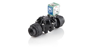
composite solenoid valve for water purification system use
Composite construction, along with other targeted features,
make the ASCO 212 Series a good choice for membrane water
purification systems and equipment.
Image courtesy Emerson - ASCO
Water purification systems and equipment present a unique set of fluid control challenges. Purified water is aggressive and will rapidly corrode most metallic parts. Additionally, strong chemicals are utilized in some systems for cleaning or regeneration, presenting yet another longevity challenge for the process valves needed to operate a system or equipment skid.

ASCO, an Emerson Brand, has developed a line of solenoid operated valves targeted at membrane based water purification applications. These applications include desalination skids and a broad range of ultrafiltration, and reverse osmosis equipment installations.

The Series 212 delivers substantial benefit to customers, through its basic construction, design and ease of use.

  • Compliance and certification listings with applicable current standards and codes.
  • Short lead time with quick-ship program from distributors.
  • High reliability - tested up to one million cycles.
  • Ease of connectivity, available as Turn & Lock, NPT thread, or solvent bond.
  • FasN connection system enables greatest equipment design and assembly flexibility.
  • Normally open and normally closed versions available.
More detail is provided in the datasheet included below. Share your fluid control challenges with process control specialists at Miller Energy, leveraging your own knowledge and experience with our product application expertise to develop effective solutions.