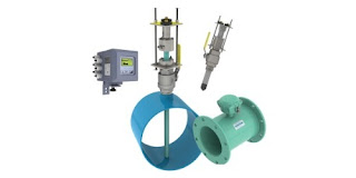
Industrial Fluid Flow Measurement

Coriolis flow meter
Coriolis flow meters deliver a mass flow measurement
Image courtesy Yokogawa
Fluid flow measurement is commonly employed in many industrial process control operations. Accurate and useful flow measurement can be obtained with the proper application and installation of a flow meter as part of the fluid transfer system.

Industrial flow meters employ differing technologies to directly or indirectly measure gas and liquid flow rates. The selection of an appropriate measurement technology and instrument will be influenced by a number of factors related to the installation and application demands.

Among the many available technologies for fluid flow measurement, vortex flow meters, magnetic flow meters, Coriolis flow meters, and rotameters are among some of the most common found in industry.

Each of the separate technologies have attributes which can make them more suitable to certain applications. Selecting the most appropriate flow measurement technology for an application is one of the initial and crucial steps to designing a well functioning flow measurement system.
Selection criteria, such as fluid temperature, pressure, and velocity will be part of the selection process. Additional considerations include whether the fluid may be abrasive, corrosive, clean or dirty. The state of the fluid, liquid or gas, must also be considered. The desired output, whether volumetric or mass flow, will certainly be an integral part of the criteria.

Selecting the right measurement technology and instrument is not always an easy task, especially since it may be something that you do infrequently. Share your flow measurement challenges and requirements with process instrumentation specialists, leveraging your own knowledge and experience with their product application expertise to save time and develop an effective solution.

Yokogawa Gas Density Analyzer and Detector Pairing


Yokogawa's Gas Density Meter is a combination of density converter and detector. The instrument provides continuous measurement of process gas density, specific gravity and molecular weight in a configuration delivering stable operation and requiring little maintenance.

One important aspect is the proper pairing of a detector with the density converter. The video explains the process and how to make sure it is done correctly.

Share your process analytical and measurement challenges with process instrumentation experts, leveraging your own knowledge and experience with their product application expertise to develop effective solutions.

Using Brooks Mass Flow Controllers with LabVIEW™

coriolis mass flow controller
Coriolis mass flow controller
Image courtesy Brooks Instrument
Brooks Instrument is the manufacturer of highly accurate and repeatable mass flow controllers. LabVIEW™ develops integrated software for building measurement and control systems used in laboratories, universities, and pilot manufacturing plants. The combination of Brooks MFCs and LabVIEW software provides users a great option for measurment, control, data acquisition and data storage for mass flow.

Listed below are some of the more convenient communication methods to tie Brooks MFCs and LabVIEW™ software together.

Analog Signal Interface

In many situations LabVIEW™ software users also use analog to digital
I/O cards. With analog input cards, users can run their mass flow controllers utilizing a standard 0-5 volt or 4-20 mA analog signaling via LabVIEW™. This is a time-tested, traditional approach and is recommended for applications without the availability of digital control systems.

RS485 Digital Interface

Brooks Instrument mass flow devices configured with RS485 communications (must have the ‘S’ communications option) provide RS485 digital communications via a 15-pin D connector. The RS485 digital signal is passed directly to a computer running LabVIEW™ through a serial RS485 converter. Brooks models GF40, GF80 and SLA Series mass flow controllers are available with the ‘S’ communications option.

Its valuable to note that there is also a free set of VI file for use with LabVIEW from Brooks. These can be loaded directly into the LabVIEW™ application and provide the basics required to create a LabVIEW control interface using the S-Protocol digital command structure. The VI files are available for download from the Brooks Instrument website.

Another communications alternative is using Brook’s Smart DDE (Dynamic Data Exchange) software tool to create links between the LabVIEW™ application and the GF40, GF80 or SLA Series flow, control, and configuration parameters. Additionally, the user can leverage Windows applications (Excel, Word, Access) and programming languages ( C++, C#, Visual Basic) and SCADA programs from suppliers such as Allesco and Millennium Systems International. No knowledge of the mass flow device S-Protocol command structure is required. With Smart DDE, the user gets direct access to the required data fields. While not a complete turnkey option, it greatly reduces the amount of code required to communicate between LabVIEW and the mass flow controller.

DeviceNet Digital Signal Interface

Brooks models GF40, GF80 and SLA, configured for DeviceNet digital communications, can also be controlled via the LabVIEW™ application provided a National Instruments DeviceNet interface card, associated drivers, and software are used. These additional items support the development of application interfaces using LabVIEW™ software for Windows and LabVIEW™ Real-Time.

According to the National Instruments website:
National Instruments DeviceNet for Control interfaces are for applications that manage and control other DeviceNet devices on the network. These interfaces, offered in one-port versions for PCI and PXI, provide full master (scanner) functionality to DeviceNet networks. All NI DeviceNet interfaces include the NI-Industrial Communications for DeviceNet driver software, which features easy access to device data and streamlined explicit messaging. Use a real-time controller such as PXI and NI industrial controllers to create deterministic control applications with the NI LabVIEW Real-Time Module.

Share your mass flow measurement and control challenges with application experts, leveraging your own knowledge and experience with their product application expertise.

Focus Your Product Selection Quickly With This Useful Tool

Yokogawa Process Instrumentation Selection Tool
The Process Instrumentation Selection Tool from Yokogawa
enables the user to make detailed product selections
with a few clicks.
Image courtesy Yokogawa
In the process measurement sphere, manufacturers respond to market demand and their own growth goals by offering integrated product solutions. This can result in a product offering that is extensive, with many different products that can be applied to the same task. There are often several, or many, choices to winnow down to a final selection. Product research and evaluation for application suitability takes time. In today's business environment, time is what we never seem to have in sufficient quantity. Finding ways to streamline any process can be beneficial.

Yokogawa is one of those companies that manufactures a broad range of products for process measurement. Whatever your process measurement needs, it is likely the Yokogawa has an effective solution that delivers solid quality and performance.

In a past blog posting, we introduced readers to Process Instrument Selection Tool. With some basic information about your application, a few clicks can quickly deliver access to the best product selection for an application. It is simple, rapid and accurate. The product selector covers 24 basic measurement and instrumentation classifications. We are posting about it again because it has been so successful in helping customers zoom in on the right product solutions for their process measurement applications.

The Product Finder is accessible through a number of links throughout Yokogawa's network of representatives. Clicking the link lands you on the start page of the Product Finder. Try it out, and share your process measurement and control challenges with application specialists for even more leveraging of your own process knowledge and experience toward an effective solution.

Fixed Gas Detectors

fixed installation gas detector sensor transmitter
Fixed installation gas sensor / transmitters.
Image courtesy 3M - Oldham
The expansion of demand for increased levels of safety in the workplace continues, with calls for better protection for workers, the plant, the environment, and surrounding communities all weighing on operators to look for ways to reduce risk. Industrial plants, especially those employing hazardous or flammable materials, can have very high risk levels. Reducing the probability of accident or failure can bring a very substantial benefit for long term operation.

Oldham, a 3M brand, manufactures fixed and portable hazardous gas detection and monitoring equipment for application in commercial and industrial settings. Their sensors and stations enable continuous monitoring of process or facility conditions and alert of potentially dangerous conditions. The application possibilities range through every industry.

The product line employs a number of technologies, with varied housings and form factors to accommodate any installation requirement. A wide range of gases can be detected and measured. Share your hazardous gas and flame detection monitoring challenges with process measurement specialists, leveraging your own knowledge and experience with their product application expertise to develop a safer solution for your facility.

Smart Output™ Module For Water System Monitoring

magnetic flowmeter variants
Full bore flanged and insertion style magnetic flowmeters,
with Smart Output™ technology to enhance their functionality.
Image courtesy McCrometer 
Water distribution systems, though mostly invisible to the general public, are highly complex infrastructure arrangements that extend to a very large number of locations throughout a service area. Monitoring the activity and operational health of the distribution system, key to maintaining high levels of efficiency and service, requires measurement instrumentation installed throughout the system.

Magnetic flowmeters are an integral part of water system instrumentation. Their advantages for use in water systems were outlined in a previous article on how magnetic flowmeters work. McCrometer is an innovator in the design and manufacture of magnetic flowmeters for water system flow measurement. Their Smart Output™ technology is available for use with full bore flanged and insertion style flowmeters to provide the information needed for modern water system operation.

  • AC or DC powered versions
  • Compatible with Sensus and Itron smart water networks
  • Enables networking of water meters throughout distribution system
  • Queries, diagnostics, and data transfer can be scheduled or on demand
  • Enables AMR (Automatic Meter Reading) and AMI (Advanced Metering Infrastructure)
The Smart Output™ function is an additional module included as part of the instrument transmitter. 

More information is available from product application specialists, with whom you should share your flow measurement challenges of all types. Leverage your own process knowledge and experience with their product application expertise to develop effective solutions.

Best Temperature Control Performance Starts With a Match of Sensor Configuration to Application

temperature sensors configured for surface temperature measurement
A specially configured temperature sensor can improve
measurement response and process control.
Image courtesy Applied Sensor Technologies
There are more temperature controlled operations than any of us could count in a lifetime, each with a set of signature performance requirements and design challenges. Matching the means of temperature measurement, the control loop characteristics, and heat delivery method to the application are essential to achieving successful operation.

Step one is to measure the process temperature. This sounds simple until you start researching products and technologies for measuring temperature. Like the temperature controlled operations mentioned previously, they are numerous. To filter the possible candidates for temperature sensing devices, consider these aspects of your application and how well a particular sensor may fulfill your requirement.
  • Response Time - How rapidly the sensor will detect a change in process temperature is a function of how the sensor is constructed and how it is installed. Most temperature sensors are enclosed or encapsulated to provide protection for the somewhat vulnerable sensing element. Greater mass surrounding the sensing element, or a shape that inhibits heat transfer from the process to the sensor, will slow sensor response. Whether the slower response time will adversely impact process operation needs to be considered. More consideration is due to the manner in which the temperature sensor assembly is installed. Not all applications involve a fluid in which the sensor assembly can be conveniently immersed, and even these applications benefit from careful sensor placement.
  • Accuracy - Know what your process needs to be effective. Greater levels of accuracy will generally cost more, possibly require more care and attention to assure the accuracy is maintained. Accuracy is mostly related to the type of sensor, be it RTD, thermocouple, or another type.
  • Sensitivity - Related to the construction, installation, and type of sensor, think of sensitivity as the smallest step change in process temperature that the sensor will reliably report. The needs of the process should dictate the level of sensitivity specified for the temperature sensor assembly.
Take a simple application as an illustration. Heat tracing of piping systems is a common function throughout commercial and industrial settings experiencing periods of cold weather. Electric heat trace installations benefit from having some sort of control over the energy input. This control prevents excessive heating of the piping or applying heat when none is required, a substantial energy saving effort. A temperature sensor can be installed beneath the piping's insulation layer, strapped to the pipe outer surface. A specially designed sensor assembly can improve the performance of the sensor and the entire heat trace control system by enhancing the response time of the temperature sensor. A right angled sheath permits insertion of the sensor beneath the piping insulation while orienting the connection head upright. A surface pad at the tip of the sheath increases the surface contact with the pipe to provide faster sensor response. The surface pad is a metal fixture welded to the sensing end of the temperature sensor assembly. It can be flat, for surface temperature measurements, or angled for installation on a curved surface, like a pipe. The increased surface contact achieved with the surface pad promotes the conduction of heat to the sensor element from the heated pipe in our illustration. This serves to reduce and improve the response time of the sensor. Adding some thermally conductive paste between the pad and the pipe surface can further enhance the performance. While the illustration is simple, the concepts apply across a broad range of potential applications that do not allow immersion of the temperature assembly in a fluid.

A simple modification or addition of an option to a standard sensor assembly can deliver substantially improved measurement results in many cases. Share your temperature measurement requirements and challenges with a process measurement specialist. Leverage your own process knowledge and experience with their product application expertise.