Electronic Displacer Liquid Level Transmitter - How it Works, When to Use It

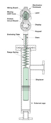
Displacer liquid level transmitter diagram
Electronic displacer liquid
level transmitter using spring
technology
Courtesy Magnetrol
An electronic displacer liquid level transmitter is intended for industrial applications requiring the continuous measurement of liquid level in a tank, vessel, or other containing space.

Magnetrol, a globally recognized leader in the design and production of level measurement instrumentation, describes the operating principle of their Digital E3 Modulevel® displacer level transmitter:
Electronic displacer level transmitter technology operates by detecting changes in buoyancy force caused by liquid level change. These forces act upon the spring supported displacer causing vertical motion of the core within a linear variable differential transformer.
The movement of the core within the LVDT generates an electrical signal which is further processed and serves as the output of the transmitter. The unit is designed to be externally mounted on a tank. Isolation valves are recommended.

The spring technology employed as a counterforce to the buoyancy of the displacer results in a stable signal that is not impacted greatly by vibration, agitation, or turbulence of the measured liquid.

The video below provides more detail, covering the features and advantages of this level measurement technology and the Magnetrol instrument. Share your level measurement challenges and requirements with a product application specialist. The combination of your process knowledge and their product application expertise will produce effective solutions.


Tank Blanketing Valve Function and Useful Features

tank blanketing valve
Tank Blanketing Valve
Caschco - Valve Concepts
The filling of vapor space in a liquid containing tank with a gas is referred to as "tank blanketing", and sometimes "padding". Specialized valves are available, designed to simplify the incorporation of a tank blanketing function in an operation.

Often, the gas employed to fill the vapor space in a tank is nitrogen. The purpose of blanketing can vary, but generally involves preservation of the stored product or safety. In both cases, one goal is to keep oxygen levels in the vapor space sufficiently low to inhibit ignition of flammable products, or minimize oxidation and its impact on stored product quality. The inflow of blanketing gas can also be used to keep the tank under positive pressure relative to the surrounding space, considered to harbor contaminants which could otherwise leak into the tank.


What are some functions of a tank blanketing valve?


  • Maintain positive pressure in the tank at a selected setpoint.
  • Provide gas control at very low flow rates, or close bubble tight, when tank liquid level is static.
  • Adjust gas flow to compensate for the maximum liquid draw down rate.
  • Provide sufficient closure to prevent supply gas from excessively pressurizing tank.
Blanketing valves are used in conjunction with vents to provide a full range of control over the pressure and content of the vapor space within a tank. A single valve solution eases the design and component selection burden of amassing individual components and combining them into a working assembly. Some useful features of a blanketing valve include:
  • Bubble tight shutoff to prevent wasting of purge gas.
  • Self cleaning flow path design.
  • Pressure balanced pilot, so supply pressure fluctuations do not impact the setpoint.
  • Setpoint not appreciably affected by changes in temperature.
  • Low maintenance requirements, including complete access to valve internals without removing the valve from the tank.
More detail, including a description of the elements required for proper valve sizing, is found in the document below. Share your fluid process measurement and control challenges with application specialists, combining your process experience and knowledge with their product application expertise to develop effective solutions.

Refrigerated Air Dryer for Compressed Air

refrigerated dryer for compressed air low dewpoint
Refrigerated Dryer for Compressed Air
Wilkerson Corporation
Compressed air, a common source of power in many industrial settings, functions best when treated in a number of ways to remove contaminants that can damage or impair downstream devices and equipment. One contaminant of concern is moisture.

When ambient air is compressed, its temperature increases, but also does the ratio of water per unit of air volume. This results in a compressed air supply with what may be an unacceptably high dew point. Dew point is the temperature at which air is saturated, and cooling air below its dew point will result in the formation of condensate (liquid water). As compressed air is consumed by usage equipment, the air pressure drops, along with the temperature. These condition changes, and others, can result in condensate formation in the compressed air system and connected equipment. This is generally considered a negative development, as the presence of excessive moisture can lead to line freezing, corrosion, excessive equipment wear, and malfunction.

There are a number of methods and technologies available to reduce the absolute moisture content of compressed air. Each has its own set of positive, as well as limiting, aspects that dictate the best way to apply the technology.

Refrigerated air dryers employ essentially the same principle used to dehumidify air in occupied spaces within commercial buildings and residences. The incoming compressed air is cooled through the use of a mechanical refrigeration system. Cooling the compressed air results in condensing a portion of it's moisture content. The chilled air is then used to pre-cool the incoming compressed air, boosting the cooling system effectiveness and increasing the temperature of the discharge air. This increase in the discharge air temperature is also helpful in preventing condensate formation on the downstream system piping.

The refrigerated air dryer is a single part of what should be a total approach to compressed air quality. Here is a schematic example.

schematic compressed air treatment components with refrigerated dryer
A refrigerated dryer is one of several components that remove contaminants from compressed air systems
More information and detail is provided in the document below. Share your compressed air system requirements and challenges with application experts, combining your process experience and knowledge with their product application expertise to develop effective solutions.


Solenoid Valves - The Operational Basics

industrial solenoid operated valves
Industrial Solenoid Valves
Magnatrol
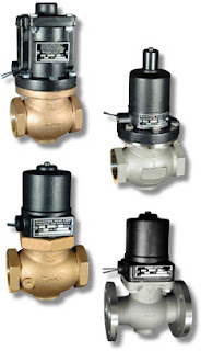
A solenoid is an electric output device that converts electrical energy input to a linear mechanical force.

At the basic level, a solenoid is an electromagnetic coil and a metallic rod or arm. Electrical current flow though the coil produces a magnetic field, the force of which will move the rod. The movable component of the solenoid is linked to, or part of, the operating mechanism of another device. This allows the switched electrical output of a controller to regulate mechanical movement in another device and cause a change in its operation. A common solenoid application is the operation of valves.

A plunger solenoid contains a movable ferrous rod, sometimes called a core, enclosed in a tube sealed to the valve body and extending through the center of the electromagnetic coil. When the solenoid is energized, the core moves to its equilibrium position in the magnetic field. The core is also a functional part of valve operation. It's repositioning causes a designed changed in the valve operating status (open or close). There are countless variants of solenoid operated valves exhibiting particular operating attributes designed for specific types of applications. In essence, though, they all rely on the electromechanical operating principle outlined here.

A solenoid valve is a combination of two functional units.
  • The solenoid (electromagnet) described above.
  • The valve body containing one or more openings, called ports, for inlet and outlet, and the valve interior operating components.
Flow through an orifice is controlled by the movement of the rod or core. The core is enclosed in a tube sealed to the valve body, providing a leak tight assembly. A controller energizing or de-energizing the coil will cause the valve to change operating state between open and closed, regulating fluid flow. There are almost countless variants of solenoid operated valves, specifically tailored for applications throughout industrial, commercial, and institutional operations.

The document provided below illustrates a portion of the broad array of solenoid valves available for industrial control applications. There are also some good cutaway illustrations showing the internal operating valve parts. Share your valve requirements and challenges with an application specialist. Combining your process application knowledge with their product expertise will produce effective solutions.

Use Electronic Pressure Controllers in Your Research Process Loop to Eliminate Droop, Boost, and Hysteresis

(re-blogged with permission from Brooks Instrument)
Gas pressure control is critical in many applications like life sciences and chemical/petrochemical research where flow is an integral part of the process. Brooks Instrument electronic pressure controllers can be used as they require flow to function. Compared to using a mechanical pressure regulator, electronic pressure controllers eliminate droop, boost and hysteresis, offering stable pressure control.

There are two configurations available for pressure control – upstream and downstream. This terminology is somewhat unique to Brooks Instrument electronic pressure controllers.

Downstream vs. Upstream Pressure Control

downstream vs upstream pressure control diagram
Downstream pressure controllers maintain the pressure downstream of the device itself, increasing flow to increase the pressure and decreasing flow to decrease the pressure. For this reason, this is called direct acting. This configuration is commonly called a standard pressure regulator. A downstream pressure controller acts very similar to a typical mass flow controller because they are both direct acting.

Upstream pressure controllers maintain the pressure upstream of the device itself, increasing flow to reduce the pressure and decreasing flow to increase the pressure. For this reason, this is called reverse acting. This configuration is commonly called a back pressure regulator in the industry.

Selecting and Sizing an Electronic Pressure Controller

The following information is required to select and size a Brooks Instrument electronic pressure controller:
  • Process gas
  • Maximum flow rate being used to maintain pressure -The “sweet spot” for pressure control is between 100 SCCM and 5 SLPM.
  • Calibration pressure (maximum pressure to be controlled)
  • Reference pressure (for upstream controllers the reference pressure is the downstream pressure and for downstream controllers the reference pressure is the upstream pressure)
As long as flow is present in a process you will typically find the need for some type of pressure control. Vessel sizes up to 30 liters commonly use flow rates up to 3 SLPM during their process steps. Brooks Instrument pressure controllers are a perfect fit for these services, offering stable pressure control with no droop, boost or hysteresis, which are commonly experienced when using a mechanical pressure regulator.


Typical Bioreactor Process Using an Upstream Pressure Controller

Magnetic Liquid Level Gauges

magnetic level indicator with auxiliary tube for guided wave radar
Magnetic level indicator with supplemental
guided wave radar instrument
Gemini Model - Magnetrol
Magnetic liquid level gauges are an excellent alternative to sight glass level gauges for many process measurement applications. Their reliable performance and adaptability has made them the primary choice in a wide variety of industrial settings.

Essentially, a magnetic level gauge or magnetic level indicator, is a sight glass with enhancements that provide better readability and a form factor that enables the inclusion of additional level monitoring functions on the same device. Where a sight glass requires operator proximity to read liquid level, the magnetic level gauge's indicating scale, or flags, can be clearly viewed from a considerable distance. A sight glass gauge can also be hindered by difficulties in visually determining liquid level because of deterioration of the glass surface or properties of the liquid. Magnetic level gauges remove the need to observe the liquid directly by incorporating a float device within a tube connected to the liquid containing vessel. As the float moves in response to liquid level changes, its magnet causes the indicator flags on the scale to rotate and display either a black face to indicate no liquid present, or a colored face.

Magnetic level indicators are available with numerous options, including armored casings to protect the tube and float arrangement and limit switches to signal the attainment of specific level conditions. Combining a MLI with another level measurement technology, such as guided wave radar or magnetostrictive, can provide an analog process signal representing liquid level and serve as a redundant measuring device for critical applications.

The document included below provides illustrated detail about the devices and their proper application. Share your process measurement requirements and challenges with instrumentation experts. The combination of your process knowledge and their product application expertise will produce effective solutions.


Comparison of RTD and Thermocouple for Process Measurement

industrial temperature sensor rtd or thermocouple
Industrial Temperature Sensor
Courtesy Wika
Proper temperature sensor selection is key to getting useful and accurate data for maintaining control of a process. There are two main types of temperature sensors employed for industrial applications, thermocouple and resistance temperature detector (RTD). Each has its own set of features that might make it an advantageous choice for a particular application.

Thermocouples consist of a junction formed with dissimilar metal conductors. The contact point of the conductors generates a small voltage that is related to the temperature of the junction. There are a number of metals used for the conductors, with different combinations used to produce an array of temperature ranges and accuracy. A defining characteristic of thermocouples is the need to use extension wire of the same type as the junction wires, in order to assure proper function and accuracy.
Here are some generalized thermocouple characteristics.
  • Various conductor combinations can provide a wide range of operable temperatures (-200°C to +2300°C).
  • Sensor accuracy can deteriorate over time.
  • Sensors are comparatively less expensive than RTD.
  • Stability of sensor output is not as good as RTD.
  • Sensor response is fast due to low mass.
  • Assemblies are generally rugged and not prone to damage from vibration and moderate mechanical shock.
  • Sensor tip is the measuring point.
  • Reference junction is required for correct measurement.
  • No external power is required.
  • Matching extension wire is needed.
  • Sensor design allows for small diameter assemblies.
RTD sensors are comprised of very fine wire from a range of specialty types, coiled within a protective probe. Temperature measurement is accomplished by measuring the resistance in the coil. The resistance will correspond to a known temperature. Some generalized RTD attributes:
  • Sensor provides good measurement accuracy, superior to thermocouple.
  • Operating temperature range (-200° to +850°C) is less than that of thermocouple.
  • Sensor exhibits long term stability.
  • Response to process change can be slow.
  • Excitation current source is required for operation.
  • Copper extension wire can be used to connect sensor to instruments.
  • Sensors can exhibit a degree of self-heating error.
  • Resistance coil makes assemblies less rugged than thermocouples.
  • Cost is comparatively higher
Each industrial process control application will present its own set of challenges regarding vibration, temperature range, required response time, accuracy, and more. Share your process temperature measurement requirements and challenges with a process control instrumentation specialist, combining your process knowledge with their product application expertise to develop the most effective solution.