Showing posts with label Delaware. Show all posts

Valves for LNG and CNG Operations

high pressure valve intended for use with natural gas
Valve specially designed for gas extraction operations
has integral bypass which equalizes pressure across the
valve prior to opening the main line, reducing torque
requirements and  piping stress.
Courtesy Habonim
The production and distribution of natural gas presents operators with substantial logistical, safety, and physical challenges. Maintaining flow control, containing, and dispensing of natural gas, CNG, and LNG are hazardous endeavors requiring special equipment configuration throughout the supply chain.

Source and pipeline operations are faced with high pressure and extreme working environments. At various points along the distribution path, valves will be needed to regulate or direct flow and isolate portions of the system for safety or service. Emergency shutdown valves must be configured and installed to provide failure-proof reliability when called upon to operate. Transportation containers and equipment will utilize specialized valves adapted for the pressure, temperature, and reliability requirements of the application and industry. Additionally, some may need to survive fire conditions without failure.

Fueling stations for compressed natural gas employ valves that will endure cold temperatures produced by gas expansion, plus dynamic pressure cycling. Bubble tight shutoff is necessary to maintain safety.

Liquified natural gas (LNG) presents many of the same application challenges as pressurized gas, with the added element of cryogenic temperatures.

All of these applications can be adequately served with a properly selected and configured valve and actuator. Share your fluid flow control and valve challenges of all types with application specialists. The combination of your process knowledge and experience with their product application expertise will produce an effective solution.


Water Quality Analysis – Constituent Survey Part 3

industrial water quality represented as bubbles
Water quality can be a concern for process input or effluent
What we know as “water” can consist of many non-H2O components in addition to pure water. This three part series has touched on some of the constituents of water that are of interest to various industrial processors. The first installment reviewed dissolved oxygen and chloride. The second article covered sulfates, sodium, and ammonia. 

To conclude the three part series on water quality analysis in process control related industrial applications we examine silica, another element which in sufficient quantities can become a confounding variable in water for industrial use. In natural settings, silica, or silicon dioxide, is a plentiful compound. Its presence in water provides a basis for some corrosion-inhibiting products, as well as conditioners and detergents. Problems arise, however, when high concentrates of silica complicate industrial processes which are not designed to accommodate elevated levels. Specifically, silica is capable of disrupting processes related to boilers and turbines. In environments involving high temperature, elevated pressure, or both, silica can form crystalline deposits on machinery surfaces. This inhibits the operation of turbines and also interferes with heat transfer. These deposits can result in many complications, ranging through process disruption, decreased efficiency, and resources being expended for repairs.

The silica content in water used in potentially affected processes needs to be sufficiently low in order to maintain rated function and performance. Silica analyzers provide continuous measurement and monitoring of silica levels. The analyzers detect and allow mitigation of silica in the initial stages of raw material acquisition or introduction to prevent undue disruption of the process. Additionally, a technique called power steam quality monitoring allows for the aforementioned turbine-specific inhibition – related to silica conglomerates reducing efficacy and physical movement – to be curtailed without much issue. The feedwater filtration couples with a low maintenance requirement, resulting in reduced downtime of analytic sequences and a bit of increased peace of mind for the technical operator.

While silica and the other compounds mentioned in this series are naturally occurring, the support systems in place to expertly control the quality of water is the most basic requirement for harvesting one of the earth’s most precious resources for use. As a matter of fact, the identification and control of compounds in water – both entering the industrial process and exiting the industrial process – demonstrates key tenets of process control fundamentals: precision, accuracy, durability, and technological excellence paired with ingenuity to create the best outcome not just one time, but each time.

Diaphragm Seals For Protection of Process and Pressure Instruments

diaphragm seal for industrial process pressure sensor or gauge
One of many diaphragm seal variants
Courtesy Wika
Pressure measurement is a common element industrial operations or control systems. Fluid processing can often involve media that is potentially harmful to pressure sensing devices. The media may be corrosive to the sensor material, or other media properties may impact the performance or usable life of the instrument. In process control environments, diaphragm seals play a role in protecting items like pressure sensors from damage by process fluids. The diaphragm seal is a flexible membrane that seals across the connecting path to a sensor and isolates the sensor from the process media. System pressure crosses the barrier without inhibition, enabling accurate measurement, but the process fluid does not. Typical materials composing diaphragm seals are elastomers, with a wide variety of specific materials available to accommodate almost every application.

In the operating principle of the diaphragm seal, the sealed chamber created between the diaphragm and the instrument is filled with an appropriate fluid, allowing for the transfer of pressure from the process media to the protected sensor. The seals are attached to the process by threaded, open flange, sanitary, or other connections.  Diaphragm seals are sometimes referred to as chemical seals or gauge guards. Stainless steel, Hastelloy, Monel, Inconel, and titanium are used in high pressure environments, and some materials are known to work better when paired with certain chemicals.

Sanitary processes, such as food, beverage, and pharmaceuticals, use diaphragm seals to prevent the accumulation of process fluid in pressure ports, a possible source of contamination. If such a buildup were to occur, such as milk invading and lodging in a port on a pressure gauge, the resulting contamination compromises the quality and purity of successive batches. Extremely pure process fluids, like ultra-pure water, could be contaminated by the metal surface of a process sensor. Some pneumatic systems rely on the elimination of even the smallest pressure fluctuations, and diaphragm seals prevent those by ensuring the separation of the process materials from the sensors.

Diaphragm seals are not without some application concerns, and devices are now built to address and counter many potential issues related to the use of diaphragm seals with process monitoring instruments and equipment. Products seek to eliminate any and all dead space, allow for continuous process flow, and are self-cleaning thanks to continuous flow design. Some high pressure seals come equipped with anti-clogging features, accomplished by the elimination of internal cavities while protecting gauges. Multi-purpose seals reduce temperature influence and improve instrument performance while pinpointing and diffusing areas of high stress. These pre-emptive measures result in longer instrument life-cycles and improved performance while ensuring protection from corrosion.

There are numerous options and available diaphragm seal variants. Share your application specifics with a product specialist, combining your own process knowledge and experience with their product application expertise to develop an effective solution.

Thermal Mass Flow Meter Q&A From Magnetrol

thermal mass flow meter
Thermatel® thermal mass flow meter
Courtesy Magnetrol®
Sometimes you discover that others do something better than you. When that happens, watch and listen.

Tom Kemme, from Magnetrol®, expertly fielded some questions about thermal mass flow meters in a recent blog post. Mr. Kemme's responses were so useful and clear that I decided, with all the credit flowing his way, to share them here for those of you that may not closely follow the Magnetrol® Blog.

Question: What is the difference between the flow units Nm3/h, Sm3/h, and actual m3/h?

Answer: Actual m3/h is a flow rate at operating temperature and pressure. Normal or standard m3/h (Nm3/h = Sm3/h) is a flow rate at standard temperature and pressure (STP). I tend to reference the natural gas industry, where it is not possible to compare flow rates at every operating condition, so it is preferable to reference all flow rates back to a set of base conditions, such as 60°F and 1 atm. STP is not universal so it may be unique based on the region or industry.

Most flow meters output a flow rate at operating conditions and need to correct this measurement. This may be accomplished with a multivariable transmitter or external to the device. A few examples that do not need to correct the measurement are thermal mass flow meters, such as the ones produced by MAGNETROL, and Coriolis flow meters.

Question: Do you have any certified failure rate data on your units to perform an SIL verification?

Answer: A Failure Modes, Effects, and Diagnostics Analysis (FMEDA) is completed during development to determine failure rates and Safe Failure Fraction (SFF). The SFF is utilized to determine Safety Integrity Level (SIL), which is often the published value.

Question: What should my meter be reading with no air flow in the pipe?

Answer: At zero flow and a dry pipe, a thermal mass flow meter should measure zero. Different thermal meters may have varying stability at no flow due to differences in operation.

There are two different types of operation: constant temperature (CT) and constant power (CP). CT devices start with a low power and this power increases with the flow rate to maintain the constant temperature difference (ΔT) between the RTDs. CP devices start with a high ΔT between RTDs at low flow and the ΔT decreases as the flow rate increases. CP may lack stability at zero flow due to possible convection currents associated with the high ΔT. CT will hold zero better, particularly devices that add less heat. For example, the maximum surface temperature of a TA2 probe is 4 C above process temperature. This is extremely low heat, eliminating convection currents due to the sensor. Convection currents could also occur through the pipe due to temperature variations.

It is also possible for a thermal meter to measure above zero during a no flow condition when there is pressure buildup in the line (typically a valve closed downstream). There may be low flow cutoff settings that can be changed to ignore nuisance measurements.


You can easily tap into Magnetrol® expertise to solve your flow measurement challenges. Reach out to a product specialist and combine your process knowledge with their flow measurement expertise to develop effective solutions.

Dynamic Compensation for Static Pressure Effects in Differential Pressure Measurement

DPharp gauge pressure transmitter
DPharp Gauge Pressure Transmitter
Courtesy Yokogawa
Attaining the best available performance and accuracy from any measuring device utilized in an industrial process is always advantageous. The scale of most industrial processes is such that even small inaccuracies in process measurement produce financially tangible impact. Differential pressure measurement, with wide application in the industrial process sphere, can be improved with the addition of a means to compensate for the real world effects of static pressure upon instrument performance.

Yokogawa Corporation has developed a means to dynamically compensate for static pressure effects in field measurements. The brief technical presentation below will help you understand how static pressure effects can impact your field measurements, as well as how Yokogawa’s Real-time Dynamic Compensation works to offset its impact.

More detailed product and application information is available from your Yokogawa specialist.


Diaphragm Pressure Gauges for Industrial Process Measurement

diaphragm pressure gauge for industrial process measurement
Example of a diaphragm pressure gauge
Courtesy Wika
Diaphragm pressure gauges, like every device and instrument intended for use in industrial process measurement and control, have their own set of attributes making them an advantageous choice for some range of applications. Silvia Weber, product manager at Wika, a globally recognized leader in the field of pressure and temperature gauges, wrote an article for Process Worldwide (process-worldwide.com/) about diaphragm pressure gauges.

The article is included below and provides a comparison of the differences between Bourdon tube and diaphragm operating mechanisms, focusing on design and operational features of diaphragm pressure gauges and the range of application criteria for which they may be the best choice.

Pressure gauges are utilized in most operations where fluids are moved through a system. Gauges, though mechanical in operation, remain a mainstay of fluid operations because of their reliability, local display, ruggedness, and lack of reliance on electric power for operation. There are countless pressure gauge configurations to suit every application. Specifying the best gauge configuration for an application is accomplished by combining your process knowledge with the application expertise of a product specialist.


Protect Valuable Pressure Gauges and Transmitters With a Pressure Limiting Valve

pressure limiting valve for gauge or transmitter protection
Pressure limiting valve provides gauge
or transmitter protection from spikes
Courtesy Mid-West Instruments
Pressure gauges and transmitters, commonly found in fluid process control operations, are vulnerable to damage from transient spikes in system pressure that may range beyond the instrument's working range. These pressure spikes can impact instrument calibration, or even render the instrument or gauge inoperative. The cost of replacing gauges or transmitters is substantial enough to warrant the use of protective devices to prevent exposure to pressure spikes.

Mid-West Instruments manufactures a line of pressure limiting valves specifically intended for use with pressure gauges and transmitters. The Model 200 pressure limiting valve prevents instrument over-range and has an adjustable needle valve to dampen pulsation. The valve and be used with all types of instruments and pressure gauges, is suitable for mounting in any position, and is available in a range of materials for body and seals.

The document below provides more product detail, as well as installation and setup instructions. Providing a useful measure of protection for pressure gauges and transmitters is a simple operation. Reach out to product application specialists for help in formulating effective solutions.


Industrial Process Gauges - New Product Guide

industrial pressure gauge
One of the many pressure gauge versions
employed throughout industry
Courtesy Ametek - U.S. Gauge
Even with the large growth in the use of electronic measurement instruments throughout the process control sphere, mechanical gauges and indicators remain an important part of process measurement and control operations.

A broad line of industrial gauges and diaphragm seals is available from U.S. Gauge. The company has consolidated its offering into a product guide that provides simple and quick reference to the various product series.

For pressure:

  • Process Gauges
  • Liquid Filled Gauges
  • Test Gauges
  • General Equipment Gauges
  • Special Application Gauges

For temperature:

  • Adjustable Bimetallic Thermometers
  • Thermowells
  • Industrial Bimetallic Thermometers
  • Multi-Angle Industrial Thermometers
  • Digital Thermometers
  • Glass Tube Thermometers
The product guide also includes diaphragm seals and a range of electronic indicators, as well.

The guide illustrates gauges for every industrial application. Share your process measurement and control challenges with product application specialists, combining your process knowledge with their product application expertise to develop effective solutions.


Basic Guide to Understanding Pressure

absolute pressure transmitter for industrial process measurement control
One style of absolute pressure transmitter
Courtesy Yokogawa
The impact of pressure on industrial processes would be difficult to understate. Pressure is an element of process control that can affect performance and safety. Understanding pressure concepts and how to effectively measure pressure within a process are key to any operator's success.

Yokogawa, a globally recognized leader in process measurement and control, has made available a handbook on pressure that covers a range of useful topics. The content starts with the very basic concepts and moves quickly to practical subjects related to process measurement and control.

The handbook will prove useful to readers at all levels of expertise. Share your process measurement challenges with application specialists, combining your process knowledge with their product application expertise to develop effective solutions.


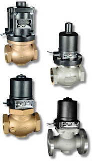
Solenoid Valves - The Operational Basics

industrial solenoid operated valves
Industrial Solenoid Valves
Magnatrol
A solenoid is an electric output device that converts electrical energy input to a linear mechanical force.

At the basic level, a solenoid is an electromagnetic coil and a metallic rod or arm. Electrical current flow though the coil produces a magnetic field, the force of which will move the rod. The movable component of the solenoid is linked to, or part of, the operating mechanism of another device. This allows the switched electrical output of a controller to regulate mechanical movement in another device and cause a change in its operation. A common solenoid application is the operation of valves.

A plunger solenoid contains a movable ferrous rod, sometimes called a core, enclosed in a tube sealed to the valve body and extending through the center of the electromagnetic coil. When the solenoid is energized, the core moves to its equilibrium position in the magnetic field. The core is also a functional part of valve operation. It's repositioning causes a designed changed in the valve operating status (open or close). There are countless variants of solenoid operated valves exhibiting particular operating attributes designed for specific types of applications. In essence, though, they all rely on the electromechanical operating principle outlined here.

A solenoid valve is a combination of two functional units.
  • The solenoid (electromagnet) described above.
  • The valve body containing one or more openings, called ports, for inlet and outlet, and the valve interior operating components.
Flow through an orifice is controlled by the movement of the rod or core. The core is enclosed in a tube sealed to the valve body, providing a leak tight assembly. A controller energizing or de-energizing the coil will cause the valve to change operating state between open and closed, regulating fluid flow. There are almost countless variants of solenoid operated valves, specifically tailored for applications throughout industrial, commercial, and institutional operations.

The document provided below illustrates a portion of the broad array of solenoid valves available for industrial control applications. There are also some good cutaway illustrations showing the internal operating valve parts. Share your valve requirements and challenges with an application specialist. Combining your process application knowledge with their product expertise will produce effective solutions.