Smart Output™ Module For Water System Monitoring

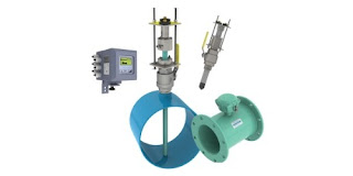
magnetic flowmeter variants
Full bore flanged and insertion style magnetic flowmeters,
with Smart Output™ technology to enhance their functionality.
Image courtesy McCrometer 
Water distribution systems, though mostly invisible to the general public, are highly complex infrastructure arrangements that extend to a very large number of locations throughout a service area. Monitoring the activity and operational health of the distribution system, key to maintaining high levels of efficiency and service, requires measurement instrumentation installed throughout the system.

Magnetic flowmeters are an integral part of water system instrumentation. Their advantages for use in water systems were outlined in a previous article on how magnetic flowmeters work. McCrometer is an innovator in the design and manufacture of magnetic flowmeters for water system flow measurement. Their Smart Output™ technology is available for use with full bore flanged and insertion style flowmeters to provide the information needed for modern water system operation.

  • AC or DC powered versions
  • Compatible with Sensus and Itron smart water networks
  • Enables networking of water meters throughout distribution system
  • Queries, diagnostics, and data transfer can be scheduled or on demand
  • Enables AMR (Automatic Meter Reading) and AMI (Advanced Metering Infrastructure)
The Smart Output™ function is an additional module included as part of the instrument transmitter. 

More information is available from product application specialists, with whom you should share your flow measurement challenges of all types. Leverage your own process knowledge and experience with their product application expertise to develop effective solutions.

Best Temperature Control Performance Starts With a Match of Sensor Configuration to Application

temperature sensors configured for surface temperature measurement
A specially configured temperature sensor can improve
measurement response and process control.
Image courtesy Applied Sensor Technologies
There are more temperature controlled operations than any of us could count in a lifetime, each with a set of signature performance requirements and design challenges. Matching the means of temperature measurement, the control loop characteristics, and heat delivery method to the application are essential to achieving successful operation.

Step one is to measure the process temperature. This sounds simple until you start researching products and technologies for measuring temperature. Like the temperature controlled operations mentioned previously, they are numerous. To filter the possible candidates for temperature sensing devices, consider these aspects of your application and how well a particular sensor may fulfill your requirement.
  • Response Time - How rapidly the sensor will detect a change in process temperature is a function of how the sensor is constructed and how it is installed. Most temperature sensors are enclosed or encapsulated to provide protection for the somewhat vulnerable sensing element. Greater mass surrounding the sensing element, or a shape that inhibits heat transfer from the process to the sensor, will slow sensor response. Whether the slower response time will adversely impact process operation needs to be considered. More consideration is due to the manner in which the temperature sensor assembly is installed. Not all applications involve a fluid in which the sensor assembly can be conveniently immersed, and even these applications benefit from careful sensor placement.
  • Accuracy - Know what your process needs to be effective. Greater levels of accuracy will generally cost more, possibly require more care and attention to assure the accuracy is maintained. Accuracy is mostly related to the type of sensor, be it RTD, thermocouple, or another type.
  • Sensitivity - Related to the construction, installation, and type of sensor, think of sensitivity as the smallest step change in process temperature that the sensor will reliably report. The needs of the process should dictate the level of sensitivity specified for the temperature sensor assembly.
Take a simple application as an illustration. Heat tracing of piping systems is a common function throughout commercial and industrial settings experiencing periods of cold weather. Electric heat trace installations benefit from having some sort of control over the energy input. This control prevents excessive heating of the piping or applying heat when none is required, a substantial energy saving effort. A temperature sensor can be installed beneath the piping's insulation layer, strapped to the pipe outer surface. A specially designed sensor assembly can improve the performance of the sensor and the entire heat trace control system by enhancing the response time of the temperature sensor. A right angled sheath permits insertion of the sensor beneath the piping insulation while orienting the connection head upright. A surface pad at the tip of the sheath increases the surface contact with the pipe to provide faster sensor response. The surface pad is a metal fixture welded to the sensing end of the temperature sensor assembly. It can be flat, for surface temperature measurements, or angled for installation on a curved surface, like a pipe. The increased surface contact achieved with the surface pad promotes the conduction of heat to the sensor element from the heated pipe in our illustration. This serves to reduce and improve the response time of the sensor. Adding some thermally conductive paste between the pad and the pipe surface can further enhance the performance. While the illustration is simple, the concepts apply across a broad range of potential applications that do not allow immersion of the temperature assembly in a fluid.

A simple modification or addition of an option to a standard sensor assembly can deliver substantially improved measurement results in many cases. Share your temperature measurement requirements and challenges with a process measurement specialist. Leverage your own process knowledge and experience with their product application expertise.

Maintenance Procedures - Yokogawa ADMAG TI Series AXW Magnetic Flowmeter

magnetic flow meter with corrosion resistant lining
The AXW series of magnetic flow meters is available in
a range of sizes with corrosion resistant lining.
Image courtesy Yokogawa
The ADMAG AXW™ series of magnetic flow meters has been developed based on Yokogawa's decades of experience in the design and manufacture of magnetic flowmeters. The AXW series continues the tradition of high quality and reliability that has become synonymous with the Yokogawa name.

The AXW series is ideal for industrial process lines, and water supply and sewage applications. With outstanding reliability and ease of operation, developed on decades of field-proven experience, the AXW will increase user benefits while reducing total cost of ownership.

Magnetic flow meters, also called electromagnetic flow meters or "magmeters", operate on a very simple principal. An electrically conductive liquid moving through a magnetic field will generate a voltage that is related to the velocity of the liquid. Magnetic flow meters have no moving parts and present little to no pressure drop to the piping system into which they are installed.

Sizes are available from 500 to 1800 mm (20 to 72 inch.) with a wide liner selection such as PTFE, natural hard rubber, natural soft rubber, and polyurethane rubber. The line accommodates industry standard process connections such as ASME, AWWA, EN, JIS, and AS flange standards. A submersible version is also available.

Care and maintenance for magnetic flow measurement devices is simple and minimal. The manual included below provides basic guidelines for maintenance procedures of ADMAG TI (Total Insight) Series AXW magnetic flowmeters. Share your flow measurement challenges with process instrument specialists, leveraging your own knowledge and experience with their product application expertise.


White Paper About Safety Compliance for Solenoid Valves

industrial solenoid valves
Solenoid valves for industrial process control applications
Image courtesy Asco Valve
Regulatory modifications have raised important issues in design and use of industrial safety systems. Certain changes in IEC 61508, now being widely implemented, mean that designers and users who desire full compliance must give new consideration to topics such as SIL levels and the transition to new methodologies.

In particular, these issues can impact the selection of solenoid valves and prepackaged redundant control systems (RCS) for implementation in a safety instrumented system (SIS). Such selections may also be affected by how experienced valve suppliers are at dealing with complex new compliance methodologies.

These issues are especially applicable to the oil, gas, chemical, and power industries - in applications such as safety shutdown systems, boilers, furnaces, high-integrity protection systems (HIPS), and more. These issues are of concern to safety engineers and reliability engineers, as well as to process engineers, engineering executives, and plant managers.

This report, a white paper made available by ASCO Valve, will address these issues in developing a compliant safety instrumented system using valves and redundant control systems. Making the right choices in safety system planning and in valve supplier selection can affect design time, costs, and effort — as well as the safety of the plant itself.


Top End Guided Wave Radar Level Transmitter

guided wave radar level transmitter
Magnetrol's model 706 embodies the best of guided
wave radar level measurement.
Image courtesy of Magnetrol
The Eclipse Model 706 is Magnetrol's loop powered high performance guided wave radar level transmitter. It incorporates many of the company's latest innovations into a single instrument capable of meeting the demanding requirements of an array of industrial applications.

Product improvements include increased signal to noise ratio, suitability for use with low dielectric media, and the ability to deliver accurate indication under foaming, flashing, or other challenging conditions. An extended probe offering enables use in measuring interface, liquified gas, even bulk solids.

The instrument is suitable for overfill applications, and does not use algorithms to infer measurements in a dead zone that may occur near the top of the probe in some other designs. The Eclipse 706 delivers true measurement right up to the process flange. Upgraded electronics allow the unit to be pre-configured prior to shipment, if requested. Additionally, the widest range of communications options is available.

For more information, share your level measurement challenges with a process measurement specialist. Leverage your own process knowledge and experience with their product application expertise to develop effective solutions.


Miller Energy Expands Capabilities With New Valve Line

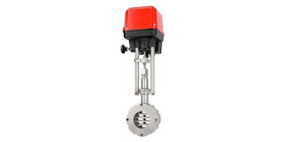
sliding gate valve with actuator
The sliding gate control valve is part of the Schubert & Salzer
product line. Image courtesy Schubert & Salzer.
Miller Energy is pleased to now represent, in the company's Pennsylvania office, Schubert & Salzer, a recognized innovator and manufacturer of high precision process flow control valves.

Schubert & Salzer specializes in precise control and stop valves for industrial fluid processing operations.
  • Sliding gate valves
  • Ball Sector Valves
  • Segment disc valves and segment disc orifices
  • Seat valves
  • Three-way valves
  • Sanitary valves
  • Pinch Valves
  • Manual valves
  • Positioners & controllers
  • Accessories to complement all products
With the expansion of its already wide range of common and specialized valve technologies, Miller Energy further solidifies its position as the go-to source for solutions to fluid process control challenges. Contact the Pennsylvania office for detailed product information. Share your challenges and leverage your process knowledge and experience with their product application expertise to develop effective solutions.


Tips For Best Control of Low Flow Rates

coriolis low flow measurement and control instrument
Low flow measurement and control instrument uses
Coriolis flow measurement sensor.
Image courtesy Brooks Instrument
Coriolis mass flow measurement is the method of choice for applications requiring best accuracy under very low flow conditions. The Quantim Series of mass flow controllers from Brooks Instrument provide indication of fluid flow, density and temperature for applications down to 0.001 Kg/hr. The instrument, in addition to a Coriolis flow sensor, provides digital signal processing, an integral or close coupled control valve, and PID control to deliver a total flow control solution in an integrated package.

Obtaining best available performance on a consistent basis is supported by a well done installation.

  • Mount the instrument to a stable surface free from excessive mechanical shock and vibration that might impact performance.
  • Locate the device where it can be easily accessed or removed.
  • Install an appropriate filter on the fluid inlet side.
  • Provide a positive shutoff valve on the downstream side to enable zeroing after installation.
  • Make sure the process flow direction matches the required flow direction of the instrument.
The sensor and control valve are designed to function properly when filled with process fluid. This means your installation cannot deliver entrapped gas in a liquid or liquid droplets in a gas. If compressed gas is used to force dosing fluids through a system, it may be necessary to provide a degassing arrangement upstream of the flow controller. Dissolved gas that flashes due to a pressure drop through the instrument can form bubbles that distort sensor and valve performance. 

Little to no maintenance is required after the instrument is installed and zeroed. The inlet filter should be changed at intervals sufficient to assure delivery of clean process fluid to the instrument.

More technical detail on the Quantim Coriolis flow measurement and control instruments is provided in the document below. Whatever your flow measurement or control application, share your challenge with measurement and control specialists, combining your own knowledge and experience with their product application expertise to leverage an effective solution.