Recording, Data Logging, and Process Control - Consolidated or Separate Devices?

Yokogawa CX2000 Integrated Controller and Data Acquisition Device
Integrated  Controller and Data Acquisition Device
Courtesy Yokogawa
Are you a designer or builder of process control systems? Selecting hardware and componentry to provide the functionality, accuracy, and accessibility required to meet process or equipment performance demands can pose some very distinct challenges. When faced with a scope of work that includes multiple PID control loops, data recording, and networking, do you tend to favor using a collection of separate devices for each function, or a consolidated unit that integrates all of the needed functions?

I have designed many control systems throughout my career, and tended toward using separate devices initially. As I gained experience and the feedback that comes from having units in the field for a number of years, my thinking changed and my preference for integrated "single box" solutions began to predominate.

Some reasons to use a consolidated device:

  • Likely to take up less panel space than a combination of individual devices.
  • Substantially reduced wiring, cabling.
  • No tasks associated with getting individual devices to work together, if that is needed. The integrated unit comes out of the box with all of that already accomplished.
  • Reduced parts count.
  • Simplified panel wiring plan.
  • A single HMI encompassing all the provided functions.
  • Anyone, end users, service techs, trainers, quality control, that needs to learn about the operation of the system has a single instruction manual to review or learn. Since the functions all come in one unit, there is often some streamlining to the learning process.
  • OEMs may be able to use a single component to provide the necessary functions for numerous product versions, bringing measurable time savings throughout the product design, fabrication, and support functions of their organization.
  • If spares are required, there is only one.
I have enjoyed good results employing devices that combine numerous functions into a single package. There is a data sheet below, so you can see more about an industrial control, recording, networking device that packs a useful range of functions into a compact unit. 

On your next process control project, consider whether going consolidated or discrete is better for your needs. Talk to a process controls expert and get some additional input. Good solutions are out there.


Five Things to Know About Process Instrument Protection

Wireless Industrial Process Instrument
Wireless Process Instrument
Courtesy Yokogawa 
The performance of every process is critical to something or someone. Keeping a process operating within specification requires measurement, and it requires some element of control. The devices we use to measure process variables, while necessary and critical in their own right, are also a possible source of failure for the process itself. Lose the output of your process instrumentation and you can incur substantial consequences ranging from minor to near catastrophic.

Just as your PLC or other master control system emulates decision patterns regarding the process, the measurement instrumentation functions as the sensory input array to that decision making device. Careful consideration when designing the instrumentation layout, as well as reviewing these five common sense recommendations will help you avoid instrument and process downtime.

Process generated extremes can make your device fail.
Search and plan for potential vibration, shock, temperature, pressure, or other excursions from the normal operating range that might result from normal or unexpected operation of the process equipment. Develop knowledge about what the possible process conditions might be, given the capabilities of the installed process machinery. Consult with instrument vendors about protective devices that can be installed to provide additional layers of protection for valuable instruments. Often, the protective devices are simple and relatively inexpensive.

Don't forget about the weather.
Certainly, if you have any part of the process installed outdoors, you need to be familiar with the range of possible weather conditions. Weather data is available for almost anywhere in the world, certainly in the developed world. Find out what the most extreme conditions have been at the installation site....ever. Planning and designing for improbable conditions, even adding a little headroom, can keep your process up when others may be down.
Keep in mind, also, that outdoor conditions can impact indoor conditions in buildings without climate control systems that maintain a steady state. This can be especially important when considering moisture content of the indoor air and potential for condensate to accumulate on instrument housings and electrical components. Extreme conditions of condensing atmospheric moisture can produce dripping water.

Know the security exposure of your devices.
With the prevalence of networked devices, consideration of who might commit acts of malice against the process or its stakeholders, and how they might go about it, should be an element of all project designs. A real or virtual intruder's ability to impact process operation through its measuring devices should be well understood. With that understanding, barriers can be put in place to detect or prevent any occurrences.

Physical contact hazards
Strike a balance between convenience and safety for measurement instrumentation. Access for calibration, maintenance, or observation are needed, but avoiding placement of devices in areas of human traffic can deliver good returns by reducing the probability of damage to the instruments. Everybody is trained, everybody is careful, but uncontrolled carts, dropped tools and boxes, and a host of other unexpected mishaps do happen from time to time, with the power to inject disorder into your world. Consider guards and physical barriers as additional layers of insurance.

Know moisture.
Electronics must be protected from harmful effects of moisture. Where there is air, there is usually moisture. Certain conditions related to weather or process operation may result in moisture laden air that can enter device enclosures. Guarding against the formation of condensate on electronics, and providing for the automatic discharge of any accumulated liquid is essential to avoiding failure. Many instrument enclosures are provided with a means to discharge moisture. Make sure installation instructions are followed and alterations are not made that inadvertently disable these functions.

Developing a thoughtful installation plan, along with reasonable maintenance, will result in an industrial process that is hardened against a long list of potential malfunctions. Discuss your application concerns with your instrument sales engineer. Their exposure to many different installations and applications, combined with your knowledge of the process and local conditions, will produce a positive outcome.

Application Advantages of Wireless Sensors for Process Measurement and Control

Industrial Wireless Access Point
Courtesy Yokogawa
Wireless sensor technology is not new, but is still in an adoptive stage in many industries. New technologies are commonly adopted first by companies and industries that can justify the premium cost of newly released technology. The adoption process is similar to that of business computers. Early models were incredibly expensive to purchase and required a very large budget to keep operational. As time passed, the machines became less expensive to purchase and own, allowing a greater segment of the business world to justify their purchase and use. Wireless process measurement and control is following a similar path, with more and more facilities considering the potential for application of these devices.

I had always considered wireless sensing devices as a great way to be rid of cabling, but limited my thinking to fixed installations. A personal confession....Sometimes it's really hard to get my mind out of the box when I tape it shut. Anyway, I came across this application case from Yokogawa, a leading worldwide manufacturer of process measurement and control equipment and an enormous array of other industrial equipment. The case study illustrates how a tire manufacturing operation used wireless sensing technology to enhance the performance of their pressure test setup. The case study, shown below, shows the actual product part numbers used and provides a schematic and description of how the system was beneficially used. After my own reading of the case, I am now thinking of more potential applications that could benefit from a wireless configuration.

Read the case, it's short and concise. A sales engineer can provide you detailed information on the specific products used in the application. If you come up with some potential wireless process measurement applications of your own, contact an application specialist and explore the possibilities.


Know Your Control Valve Basics?

Industrial Control Valve Cutaway View
Courtesy Cashco
Understanding basic operation and function of control valves, an integral part of many industrial process control loops, is essential for the process engineer, operator, or other stakeholder. This presentation outlines control valve operation, major components, and terminology used to describe valve parts, functions, and principles of operation. A useful reference for stakeholders in need of a refresher course in order to understand what the engineers are saying, it also provides detailed illustrations, charts, and description that will prove valuable to the more technical minded.


What you will find:


  • Terminology: A glossary of terms commonly used in the control valve world.
  • Control Valve Basic Designs: Control valve classifications, cutaway illustrations showing the operating structure of different valve types, comparisons of varying valve designs.
  • Characterization and Trim Design: Flow characteristic curves and comparisons for different valve types, showing how flow responds to valve position change.
  • Control Valve Technical Considerations: FTC vs FTO, illustrations showing valve operation.
  • Force-Balance Principle: Illustration and formula explanations of this basic operating principle.
  • Actuator Basic Designs: Illustrations showing the differing arrangements for actuator operation.
  • Control Valve Unit Action: Illustrations, diagrams, and explanations of a range of valve operating conditions, including loss of electrical power and loss of instrument air supply.
  • Actuator Benchset Range: Shows practical relationship between instrument air pressure and valve ability to properly operate at various pressure conditions.
  • Valve Positioner Basics: Definition of valve positioning, reasons to use a positioner, schematic illustrations of control loops.
  • Control Loop Action: Charts and provides examples of 16 combinations of Process, Controller, Positioner, and Control Valve combinations.
  • Control Valve Packing Designs: Describes and defines packing, common problems, current state of the art. Cutaway illustrations of various packing arrangements.
  • Seat Leakage: Classifications, comparisons of different materials.


There is something of value in the document for everyone, and you will undoubtedly pick up something useful. Thanks go out to the engineers at Cashco for putting this together. You can discuss any aspect of your control valve applications with a product specialist. Your contact is always welcome.


Eliminate Glass Tube Level Gauge Maintenance Costs


Magnetic Level Indicators
Courtesy Orion Instruments
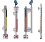
Industrial process control often requires the accurate measurement of liquid level within a tank or other vessel. There are numerous device technologies and vendors from which to choose. A recent post on this blog detailed one of the available methodologies, the magnetic level indicator. I urge you to review that short post to familiarize yourself with the operating principles and advantages of applying a magnetic level indicator, not only on future projects, but as a possible replacement of some of your existing level indication instruments.

Orion Instruments, a Magnetrol company, has authored a case study showing how the replacement of glass tube level gauges with magnetic level indicators can reap substantial cost savings over the product lifetime. The case study, included below, takes but one minute of your time to read, and delivers a compelling incentive to consider magnetic level indicators (MLI) for your new projects, even as cost saving replacements for existing glass tube level gauges.

Read the case study. Contact a product specialist to discuss your application for new or replacement level indicators.


Magnetic Level Indicators - Knowledge Base and Selection Guide

Orion Instruments Magnetic Level Indicators
Magnetic Level Indicators
Courtesy Orion Instruments
Industrial process control frequently involves the storage of liquid in vessels or tanks. Continuous and accurate indication of liquid level within the tank is an essential data point for safety and process management. While there are a number of methods and instrument types utilized to provide tank level measurement, the instrument of choice is often a magnetic level indicator, also referred to as a magnetic level gauge. Its use for providing level indication has a number of positive attributes:


  • Construction that is resistant to breakage.
  • Measuring indicators, switches, and transmitters mounted externally, without contacting the medium being measured.
  • Maintenance free operation. No regular cleaning needed.
  • Readable level indication from greater distance than glass sight gauges.
  • Magnetic level indicators can accommodate greater fluid level ranges without the need for multiple instruments.


Orion Instruments, a Magnetrol company and industry leader, has produced a comprehensive guide to magnetic level gauges, switches, transmitters, and related products. It delivers experts and newcomers an understandable and clear description of the technology and principals of operation behind magnetic level gauges and instruments. The guide also assists the reader in properly specifying and selecting the best instrument configuration for an application. A table of contents at the front of the document helps readers to quickly find the information they need.

Take a couple minutes to roll through the document and you are likely to find new and useful application tips and product information. Any questions about magnetic level indicators or your process measurement and control applications can be clearly addressed by a product specialist.


Process Gas Chromatograph with Practical Implementation of Parallel Chromatography

Process Gas Chromatograph - Yokogawa
GC8000
Process Gas Chromatograph
Courtesy Yokogawa Corp.
Gas chromatography is a common analysis tool employed in many areas of industry, including oil and gas, pharmaceutical, chemical, and others. Yokogawa Corporation of America has developed and been delivering top tier GC performance with their GC8000 Process Gas Chromatograph for use in oil and gas, and other industrial applications.

In addition to the ruggedness and reliability for which Yokogawa gas chromatographs are well known, the GC8000 brings a number of innovations and improvements to the company’s process gas chromatography product offering.

> Color touchscreen HMI for easy operation

> Advanced predictive diagnostics and software functions monitor key performance indicators during each analysis to verify analyzer is operating within proper tolerances.

> Parallel chromatography is made practical through the use of the GC Modules provided as part of the GC8000. Virtual GCs can be set up inside a single GC with GC Modules to measure multiple streams simultaneously.

The graphics below expand on this overview of the GC8000 Process Gas Chromatograph, the culmination of Yokogawa’s 55 years of experience in the field. For more detailed information, or to discuss your application specifics, contact a product specialist.