New Level Transmitter From Orion Instruments

Orion magnetostrictive level transmitter
Direct insertion and external mount versions of
Orion JM4 Magnetostrictive Level Transmitter
Courtesy Orion Instruments
Orion Instruments, a world class manufacturer of magnetic level indicators, level switches, and level transmitters, has released a new product for use in the industrial process measurement and control field. Their Jupiter Model JM4 magnetostrictive transmitter incorporates the company's many years of research, development, and field experience to provide a safer, simpler, and smarter transmitter for liquid level measurement and control.

The new model from Orion boasts level measurements with accuracy as high is +/-0.05" (1.27mm). The transmitter head can be rotated up to 310 degrees with an option for remote mounting. Variants are available for direct insertion or external mounting, with approvals for a number of area classifications. There are other valuable features to this series of level measurement instruments that reflect Orion's expertise in the field.

Browse the new product brochure included below. It provides illustrations of the product and its operating principle, along with dimensioned drawings and a listing of all the product options and variants. You can always obtain whatever information you need about Orion level measurement instruments from a product specialist. Share your liquid level measurement challenges and requirements with them for recommendations on the best solutions.


Coriolis Mass Flow Meter - Operating Principle, Applications, Advantages

Coriolis flow meter by Yokogawa
Coriolis Flow Meter - Courtesy Yokogawa
Coriolis mass flow meters are widely used throughout the process measurement and control field. Their basic operating principle, combined with modern sensor and signal processing technology, provide a list of positive aspects.

Directly measure mass flow rate based on the principle of measurement.

Measure the mass flow rate with high accuracy of ±0.1%.

Provide a wide usable measurement range.

Deliver density measurement based on oscillating frequency.

Not materially impacted by fluid viscosity or density.

Coriolis flowmeters also do not need straight pipe sections upstream or downstream of the flowmeter. They also have the ability to measure non-conductive fluids. 

I have included an interesting video, produced by Yokogawa, a world class manufacturer of industrial process measurement and control instrumentation. It provides a clear and insightful illustration of the Coriolis principle and how it is used to provide accurate mass flow measurement.

Share your process measurement and control challenges with an instrumentation specialist. Combining your detailed process knowledge and their product application expertise will yield positive solutions.


Miller Energy Expanding Customer Connectivity With New Website Function

Engineering technician inspecting precision part
At Miller Energy, use website chat to connect directly with technicians
and product specialists.
Miller Energy will be rolling out real time chat on their website in early February. This new feature is another in a long line of continuous improvements the company has brought on line to better serve and connect with their customer base. On the desktop version, a chat widget will appear on every website page as a small tab on side of the display. A click of the widget will open a chat window and the visitor can type in their question or comment. Site visitors using mobile devices are afforded the same functionality.

Steve Collins, the Miller Energy website designer at CMS4i, commented on MEI's increased level of connectivity..
"The chat implementation at Miller Energy is notable because it connects customers directly with technically qualified employees that are part of the day to day company operations. Customers will be communicating with real “hands on” engineers and specialists familiar with process measurement and control, and engaged in the field on a daily basis."
Look for the chat function on the Miller Energy website in early February. Use it to get fast answers to your questions from knowledgeable and engaged industry professionals.

Pressure Relief Valve - Guardian of the Vessel

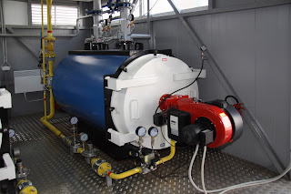
Gas fired industrial boiler
Pressure relief valves protect this industrial boiler
from conditions beyond maximum allowable working pressure
Danger and hazards are an integral part of industrial processes. The mitigation of these dangers and hazards, as well as reducing the probability of their occurrence, is the primary charge of industrial process engineering. Every product intended for use in a process control setting has safety and protection included in its design criteria. Pressure relief valves fall in that category of products designed and intended solely for safety purposes.

Manufacturers of what most generally refer to as pressure relief valves break the genre down into two distinct groups, relief valves and safety valves. One manufacturer, Anderson Greenwood (a Pentair brand), distinguishes the two valve types in their "Pentair Pressure Relief Valve Engineering Handbook"...
Relief Valve: A pressure relief valve characterized by gradual opening or closing generally proportional to the increase or decrease in pressure. It is normally used for incompressible fluids.
Safety Valve: A pressure relief valve characterized by rapid opening or closing and normally used to relieve compressible fluids.
The difference between the two valve types is found in their response to an excessive pressure condition. The relief valve, according to the definition, responds proportionally to the pressure increase, whereas the safety valve provides a non-proportional rapid response. Note also that the relief valve is generally intended for use with liquids (incompressible) and safety valves are commonly applied to compressible fluids, which would include steam and air.
pilot operated pressure relief valve
Pilot Operated Pressure Relief Valve
Courtesy Anderson Greenwood

Pressure relief valves are found anywhere pressure is contained, be it a piping system, vessel, even a
household pressure cooker. The purpose of the relief or safety valve is to protect a pressurized system or vessel, should the system pressure exceed the maximum allowable working pressure. Simply put, keep it from breaking apart.

Because of the potentially catastrophic nature of a pressurized system failure, there is a high level of scrutiny, regulation, and testing focused on pressure relief and safety valves. The proper sizing and selection of the valves is also critical to providing proper function.

I have included a product bulletin from Anderson Greenwood with this article. Browse through it. It provides solid technical information, along with some excellent cutaway illustrations showing how the valves function. You are bound to discover something you did not know about safety and relief valves and their proper application. You can also contact the specialists at Miller Energy for assistance in proper valve sizing and selection.


Measuring Flare Gas Mass Flow

Industrial Thermal Mass Flow Meter for flare gas applications
Model TA2 Thermal Dispersion
Mass Flow Meter
Courtesy Magnetrol
Industrial processing of fluids often requires the measurement of mass flow. Whether for purposes of process control or regulatory compliance, accurate measurement of fluid mass flow is an important element of industrial processing.

In the oil and gas industry, hydraulic fracturing operations release substantial quantities of natural gas. Gas wells will coincidentally release gas during completion, called flow back. Gas is also a common byproduct of oil wells and a number of other processes unrelated to petroleum production. Some operations lack the equipment and infrastructure to collect the unwanted gas and it is flared off (burned) or vented.

Compliance with state and federal regulations imposes requirements on numerous industry segments to conduct certain measurements of gas quantities flowing to different points of processing, release, or transfer. The regulatory requirements are stringent, and present a challenge to the manufacturers of mass flow measurement instruments and process engineers to achieve a cost effective solution in the face of:
  • Highly Variable Flow Rates - Production can range  from near zero to extreme bursts during upset conditions.
  • Variable Media Temperature - Depth of the gas source, or another factor, can impact temperature
  • Low Process Pressure - The flare headers usually operate near atmospheric pressure
  • Variable Composition - The components and density of the gas can change over time.
  • Difficult Maintenance - Instruments may need to be installed at locations that are hazardous and not easily accessed
The best mass flow measurement solution will effectively accommodate the challenges at each site. Thermal mass flow measurement is one technology that provides a good approach. Examine the paper included below, documenting performance of the TA2 Model manufactured by Magnetrol. Thermal mass flow measuring devices offer cost and other advantages over several competing technologies. 

Share your mass flow measurement challenges with a product application specialist. Combine your process knowledge with their product application expertise to develop the best solution. 

Simple Field Verification of Thermal Mass Flow Meter Calibration

Magnetrol brand industrial thermal mass flow transmitter for measuring mass flow of air and gases
Magnetrol TA2 Thermatel
Thermal Mass Flow Transmitter
Courtesy Magnetrol
In processes that require mass flow measurement of gases or air, thermal dispersion measurement technology is often selected for use. Its direct mass flow measurement and other attributes make this technology a favorable alternative for many applications, including combustion air, compressed air, natural gas, aeration air, vent lines, biogas production, vent lines, hydrogen lines, and more.

schematic of dual sensors on thermal mass flow meter
Schematic depiction of dual
temperature sensors on a
thermal mass flow meter
Courtesy Magnetrol
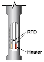
As it name implies, a thermal mass flow meter calculates flow by using temperature measurements. Two temperature sensors are inserted into the flow path. One measures the media temperature, the other is heated by a measured power source. With a device factory calibrated for a specific medium, the amount of heat transferred away from the heated sensor can be known, and will be proportional to the mass flow rate of the medium.

Some of the key attributes of thermal mass flow measurement devices:

  • Comparatively moderate initial cost
  • Compatible with measurement of low density gases that cannot be achieved with some other methods
  • Provides direct mass flow measurement
  • Most devices have option for output of process temperature
  • High turndown, with strong signal at low flow rates
  • Field calibration verification
Verifying the proper operation of transmitters of any type can be challenging, especially if performed in the field. The video below demonstrates how the Magnetrol TA2, a thermal mass flow transmitter, can have a calibration verification performed on site with a simple procedure.

The video is short and concise, with some valuable technical knowledge to build your understanding of how this technology works. More detailed information about mass flow measurement, or the specific devices shown in the video, is available from a product application specialist. Share your process measurement and control challenges with them and collaborate to develop the best solution.


Factors For Selecting a Variable Area Flow Meter (Rotameter)

Industrial process variable area flow meters rotameters
Three of many configurations of
variable area flow meters.
Courtesy Brooks Instrument
Industrial processes have many instances where fluid product components, liquid or gaseous, are moving within pipes. Processing is about control, so it follows that an input to the control, measurement, or data logging centers of the facility will answer the question, "How much is flowing through that pipe?".

There are numerous methods employed for quantifying flow in the industrial process measurement and control field, each with particular attributes that may be considered advantageous under  certain operating conditions. All flow measurement methods are indirect, as their actual measurement is of a property that is impacted in a predictable manner by a change in the flow. Flow measurement is an essential element that, combined with other fluid attributes, is used to calculate the total mass of a fluid that has traversed the measurement point.
One time tested method of measuring flow is the variable area meter, also called a rotameter.
Operation of the variable area meter (also referred to as a VA meter) is based upon creating an equilibrium between an upward force, produced by the fluid motion, and a downward force, gravity. The device includes a tapered glass or metal tube that encases a specially shaped float, often referred to as a shaped weight. VA meters must be installed vertically, with the media flowing from the bottom upward, so that the gravitational force necessary for operation is properly aligned with the flow direction. As fluid flows upward through the specially tapered tube, it creates drag on the float contained within the tube, lifting it upward. As the float rises, the free area between the float and the tube wall increases, causing a reduction in the fluid velocity and drag force. For any given flow volume, the flow velocity within the tube will cause the weight to rise until the drag force created by the flow reaches equilibrium with the countervailing force of gravity on the float. Proper design of the tube and the float allow for direct indication of flow volume.

Some of the attributes of variable area meters include:

  • No external power or fuel required for operation
  • Must be installed vertically, with flow entering bottom
  • Meters are characterized to a specific substance, at a specific temperature
  • Operation is stable, with low pressure drop
  • Requires constant gravity for operation
  • Direct local readout of flow rate with meter or scale imprinted on tube
  • Glass tube based unit flow readings require visibility of float through the medium
  • Accuracy is comparatively low for an industrial flow measurement device
  • Generally low maintenance, simple construction, low comparative cost
Brooks Instrument, a world renowned manufacturer of flow, pressure, and level measurement instruments, has produced a concise and compact white paper that summarizes the factors to consider when specifying a VA meter, as well as how each factor impacts operation of the unit. The description is practical and easily understood. It is recommended reading for all process stakeholders to build their flow measurement knowledge.

I have included the paper below. Browse the paper. Contact the flow instrumentation specialists to discuss your application requirements and challenges. Combining your process know-how with their product application knowledge will produce a good solution.