Develop a Thoughtful and Comprehensive Alarm Plan for Process Control Operations

Petrochemical piping at industrial processing plant with process control
Petrochemical plants are one of many industrial process
control operations to benefit from comprehensive alarm plans
Industrial process control operators and designers have the capability to measure many aspects of machine operation and process performance. Determining the elements to measure, method of measurement, and how to handle and process the derived information can be challenging, but can also impact the security, performance, and safety of an operation. A plan for monitoring, reporting, and responding to abnormal process conditions, if properly developed and executed, can yield real benefits to a process operator. A protocol that is not well conceived may produce a negative operational impact by creating events that unnecessarily draw resources away from productive endeavor. That protocol, or plan, is often referred to as an alarm plan.

There are numerous forces that can influence the development and implementation of an alarm plan. Each operation must incorporate its own set of external regulatory requirements, internal procedures and policies into a complete alarm protocol. Distilling that macro description down to a workable set of procedures and response tasks is where the real work begins. There is, however, a basic framework that can help organize your thinking and focus on what is most important.

  • What parameters define the process or operation?
    Produce a schedule of every non-human element that is required to make the process function. This will require drilling down through every machine and material that is part of the operation. Expect the schedule to be extensive, even huge. If it is not, consider that your analysis may not be reaching deep enough. The goal here is to create an overview of what makes the process work and provide a tool for systematically studying the process elements and gleaning possible commonalities or relationships among them. Consider disregarding things that cannot be measured, since that prevents the derivation of data for evaluation. Review the completed schedule and decide which parameters shall be measured and evaluated for proper performance.
  • What level of measurement is needed for each monitored parameter?
    An assessment of the needed accuracy, frequency, and resolution for parameter measurement will help define the requirements for instrumentation or other devices used to monitor a particular item. The goal is to make sure the monitoring device is capable of detecting and delivering information of sufficient quality to make decisions.
  • Define the limits of acceptability for each monitored parameter.
    Until the endpoint of the process or operation, each step is likely dependent in some way on previous steps. The output of each step becomes the input of the next. While this, in many cases, may be an oversimplification, it is important to consider the relationships between the tasks and operations that comprise the process. Monitored parameters should relate to the successful completion of a process step, though not necessarily be a direct indicator of success. The maintenance of the parameter within certain bounds may be used as an indicator that a component of successful completion was properly attained. Defining limits of acceptability may involve an element of subjectivity and will likely be customized to accommodate the process. Each organization shall evaluate their operation and determine limits based upon intimate process knowledge and experience.
  • Define abnormal operation for each monitored parameter.
    Abnormal operation may not necessarily be any value not within what is considered acceptable. Consider abnormal to be the range of values that would be cause for notification of the operator, or even automated or human intervention. Note that the definition of unacceptable or abnormal operation might appropriately include filters or defined relationships with other parameters. An example of a simple filter is a time delay. If the measured variable exceeds the specified limit for 2 seconds, it make not be significant. If the threshold is exceeded for 2 minutes, it may be cause to take action. As with the limits of acceptability, developing the definition of abnormal operation for each parameter will be customized for each process.
  • Provide a defined response for every alarm occurrence.
    If it is important to monitor something, then it is likely important to do something when things get out of hand. Human executed alarm response should be concise and uncomplicated, to reduce the probability of error. Automated response should be designed in a manner that provides for functional testing on a regular basis. The scope of the response will be specific for each process, with the level of response depending upon factors determined by the process operators. Response can be as simple as annunciating the condition at a monitoring station, or as dire as shutting down part or all of the process operation.
  • Review every alarm event.
    Each alarm event should be logged and reviewed. Consider whether the event detection and response was adequate and beneficial. If the results were less than expected or desired, assess whether changes can be made to provide improved results in the future. The alarm plan is unlikely to be perfect in its first incarnation. Be prepared to reevaluate and make changes to improve performance.
The exercise of developing a comprehensive alarm plan will help to build understanding of process operation for all involved parties. This article is but a brief synopsis of the subject, intended to get the reader on the path of developing a useful alarm plan. Your alarm plan should an extension of process operation decision making, and have a goal of enhancing safety and reducing loss. Contact the process control and combustion specialists at Miller Energy for additional input.

Defending Industrial Control Systems From Cyber Attack

cybersecurity for industrial control systems
Cybersecurity is now a design element of all industrial
control systems
Industrial control system owners, operators, and other stakeholders should be aware of their exposure to malicious intrusion and attack by individuals or organizations intent on inflicting physical damage, stealing information, or generally wreaking havoc throughout an industrial operation. The risk of intrusion, regardless of the size or type of facility, is real and deserves the focused attention everyone involved in the design and operation of industrial control systems.

The National Cybersecurity and Communications Integration Center, part of the US Department of Homeland Security, ...
serves as a central location where a diverse set of partners involved in cybersecurity and communications protection coordinate and synchronize their efforts. NCCIC's partners include other government agencies, the private sector, and international entities. Working closely with its partners, NCCIC analyzes cybersecurity and communications information, shares timely and actionable information, and coordinates response, mitigation and recovery efforts. (from www.us-cert.gov/nccic)
The NCCIC has published a set of seven basic steps toward establishing a more secure industrial control system. I have included the publication below, and it is interesting and useful reading for all involved in industrial process control.

Having a fence around an industrial site, with a guarded entry gate, no longer provides the level of security needed for any industrial operation. Read the seven steps. Take other actions to build your knowledge and understanding of the risks and vulnerabilities. Cybersecurity is now another layer of design tenets and procedures that must be added to every control system. It will be a part of your company's best practices and success, now and in the future.

There are uncountable legacy controllers and communications devices throughout industrial America. All need to be reassessed for their vulnerability in the current and upcoming security environment. When reviewing your processes and equipment, do not hesitate to contact Miller Energy for assistance in your evaluation of our products.


LOGIIC - Cybersecurity Confederation for Industry Video

oil refinery with tanker ship
Oil Refinery
In response to the challenges presented by malicious or mischievous cyber operatives, a number of organizations joined together to collaborate in the design, testing, and implementation of tools and techniques to protect critical industrial systems on a global scale. LOGIIC (Linking Oil and Gas Industry to Improve Cybersecurity), as its name implies, focuses on the oil and gas industry. We should all know, however, that a substantial portion of the automation and process control devices we regularly utilize throughout many industries today were originally developed in the oil and gas industry, where the operational scale and risk level are sufficiently high to justify the costs of developing new technology, methods, and equipment.

LOGIIC participants include the Automation Federation, which brings the resources of world class device and software manufacturers to bear on cybersecurity issues of the day. The Cyber Security Division of the Science & Technology Directorate in the US Department of Homeland Security is also involved. Currently, five major oil companies are members.

Since its inception, LOGIIC has successfully completed eight major projects, with plans for many more. Upon completion of selected projects, LOGIIC delivers public reports to help elevate best practices across the entire industry. Both the member companies and the government are putting funds towards these projects which benefits not only the private sector, but also the public interest. Companies are applying the results within their organizations, because it helps bridge the gap between information technology and the industrial-environment sides of the organization.

LOGIIC is an organization that conducts activities and disseminates information that can be useful throughout your own organization and that of your customers and suppliers in the industrial process control field. Below is a video highlighting the organization and its work.

Video Reenactment and Analysis of Explosion at Chemical Storage Facility

Abstract image of explosion
Unfortunate events can provide useful lessons for industrial
process operators
Industrial accidents range in severity and impact from minuscule to catastrophic. As operators, owners, or technicians involved with industrial operations, we all have a degree of moral, ethical, and legal responsibility to conduct our work in a manner that does not unduly endanger personnel, property, or the environment. Maintaining a diligent safety stance can be helped by reviewing industrial accidents at other facilities. There is much to learn from these unfortunate events, even when they happen in an industry that may seem somewhat removed from your own.

The U.S. Chemical Safety Board, or CSB, is an independent federal agency that investigates industrial chemical accidents. Below, find one of their video reenactments of an explosion that occurred in Texas in 2013, along with their findings regarding the cause of the incident. Check out the video and sharpen your senses to evaluate potential trouble spots in your own operation.

Contact Miller Energy for any safety related information you may need concerning their lines of industrial process control products.


New Product - Model R96 Non-Contact Radar Level Transmitter

Non Contact radar level transmitter Magnetrol
New Model R96 Non-Contact Radar
Level Transmitter
Courtesy Magnetrol International
Magnetrol is a well known manufacturer of level and flow measurement instrumentation for the industrial process control field. The company recently released the Model R96 Non-Contact Radar Level Transmitter for applications where continuous fluid level measurement is required.

The company's description of the product...
"Virtually unaffected by the presence of vapors or air movement within a vessel’s free space, the two-wire, loop-powered, 6 GHz Radar transmitter measures a wide variety of liquid media in process conditions ranging from calm product surfaces and water-based media to turbulent surfaces and aggressive hydrocarbon media."
 The new product offers features that combine to make a state-of-art instrument for accurate continuous level measurement. A product brochure is included below. Contact application specialists to formulate the right product configuration for your level measurement challenge.


Preparation of Control Valves For Oxygen or High Purity Service

Specialty industrial control valves
Many valves can be specially prepared for high purity or oxygen service
Oxygen is used extensively throughout a wide range of industrial processes. Medical, deep-sea, metal cutting, welding, and metal hardening are a few examples. The steel industry uses oxygen to increase capacity and efficiency in furnaces. As a synthesis gas, oxygen is also used in the production of gasoline, methanol and ammonia.

Odorless and colorless, oxygen is concentrated in atmospheric air at approximately 21%. While O2, by itself, is non-flammable, it vigorously supports combustion of other materials. Allowing oils or greases to contact high concentrations of oxygen can result in ignition and possibly explosion. Oxygen service preparation of an industrial valve calls for special cleaning processes or steps that remove all traces of oils and other contaminants from the valve to prepare for safe use with oxygen (O2). Aside from the reactive concerns surrounding oxygen, O2 preparation is also used for applications where high purity must be maintained and valves must be free of contaminants.

Gaseous oxygen is noncorrosive and may be used with a variety of metals. Stainless steel, bronze and brass are common. Liquid oxygen presents unique challenges due to cryogenic temperatures. In this case, valve bodies, stems, seals and packing must be carefully chosen.

Various types of valves are available for oxygen service, along with a wide array of connections, including screwed, socket weld, ANSI Class 150 and ANSI Class 300, DIN PN16 and DIN PN40 flanged ends. Body materials include 316 stainless steel, monel, bronze and brass. Ball and stem material is often 316 stainless steel or brass. PTFE or glass filled PTFE are inert in oxygen, serving as a common seat and seal material employed for O2 service.

Common procedures for O2 service are to carefully deburr metal parts, then meticulously clean to remove all traces of oil, grease and hydrocarbons before assembly. Valve assembly is performed in a clean area using special gloves to assure no grease or dust contaminates the valve. Lubricants compatible with oxygen must be used. Seating and leakage pressure tests are conducted in the clean area, using grease free nitrogen. Specially cleaned tools are used throughout the process. Once assembled, the valves are tested and left in the open position. A silicone desiccant pack is usually inserted in the open valve port, then the valve ports are capped. A warning label about the desiccant pack's location is included, with a second tag indicating the valve has been specially prepared for oxygen service. Finally, valves are individually sealed in polyethylene bags for shipment and storage. Different manufacturers may follow slightly differing protocols, but the basics are the same. The valve must be delivered scrupulously contaminant free.

The O2 preparation of valves is one of many special production variants available to accommodate your special application requirements. Share your valve requirements and challenges with a valve specialist to get the best solution recommendations.

Process Automation: Valve Actuator Limit Switches

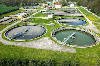
municipal water treatment plant
Municipal water treatment plant
Limit switches are devices which respond to the occurrence of a process condition by changing their contact state. In the industrial control field, their applications and product variations are almost countless. Essentially, the purpose of a limit switch is to serve as a trigger, indicating that some design condition has been achieved. The device provides only an indication of the transition from one condition to another, with no additional information. For example, a limit switch triggered by the opening of a window can only deliver an indication that the window is open, not the degree to which it is open. Most often, the device will have an actuator that is positively activated only by the design condition and mechanically linked to a set of electrical contacts. It is uncommon, but not unknown, for limit switches to be electronic. Some are magnetically actuated, though most are electromechanical. This article will focus on limit switch designs and variants used in the control and actuation of industrial process valves.
Employed in a wide range of industrial applications and operating conditions, limit switches are known for their ease of installation, simple design, ruggedness, and reliability.
Valves, devices used for controlling flow, are motion based. The movable portions of valve trim create some degree of obstruction to media flow, providing regulation of the passage of the media through the valve. It is the movement of critical valve trim elements that limit switches are used to indicate or control. The movable valve trim elements commonly connect to a shaft or other linkage extending to the exterior of the valve body. Mounting electric, hydraulic, or pneumatic actuators to the shaft or linkage provides the operator a means to drive the mechanical connection, changing the orientation or position of the valve trim and regulating the media flow. Because of its positive connection to the valve trim, the position of the shaft or linkage is analogous to the trim position and can be used to indicate what is commonly referred to as “valve position”. Limit switches are easily applied to the valve shaft or linkage in a manner that can provide information or direct functional response to certain changes in valve position.
In industrial valve terms, a limit switch is a device containing one or more magnetic or electrical switches, operated by the rotational or linear movement of the valve.
What are basic informational elements that can be relayed to the control system by limit switches? Operators of an industrial process, for reasons of efficiency, safety, or coordination with other process steps, may need answers to the following basic questions about a process control valve:
  • Is the valve open?
  • Is the valve closed?
  • Is the valve opening position greater than “X”?
  • Has the valve actuator properly positioned the valve at or beyond a certain position?
  • Has the valve actuator driven the valve mechanism beyond its normal travel limits?
  • Is the actuator functioning or failing?
Partial or complete answers to these and other questions, in the form of electrical signals relayed by the limit switch, can serve as confirmation that a control system command has been executed. Such a confirmation signal can be used to trigger the start of the next action in a sequence of process steps or any of countless other useful monitoring and control operations.

Applying limit switches to industrial valve applications should include consideration of:
  • Information Points – Determine what indications are necessary or useful for the effective control and monitoring of valve operation. What, as an actual or virtual operator, do you want to know about the real time operational status of a valve that is remotely located. Schedule the information points in operational terms, not electrical switch terms.
  • Contacts – Plan and layout a schedule of logical switches that will provide the information the operator needs. You may not need a separate switch for each information point. In some cases, it may be possible to derive needed information by using logical combinations of switches utilized for other discrete functions.
  • Environment – Accommodate the local conditions and hazards where the switch is installed with a properly rated enclosure.
  • Signal – The switch rating for current and voltage must meet or exceed those of the signal being transmitted.
  • Duty Cycle – The cycling frequency must be considered when specifying the type of switch employed. Every switch design has a limited cycle life. Make sure your selection matches the intended operating frequency for the process.
  • Auxiliary Outputs – These are additional contact sets that share the actuation of the primary switch. They are used to transmit additional signals with specifications differing from the primary signal.
  • Other Actuator Accessories – Limit switches are often integrated into an accessory unit with other actuator accessories, most of which are related to valve position. A visual local indication of valve position is a common example.
Switches and indicators of valve position can usually be provided as part of a complete valve actuation package, provided by the valve manufacturer or a third party. It is recommended that spare contacts be put in place for future use, as incorporating additional contacts as part of the original actuation package incurs comparatively little additional cost.

Employing a properly configured valve automation package, with limit switches delivering valve status or position information to your control system, can yield operational and safety benefits for the life of the unit. Good advice is to consult with a valve automation specialist for effective recommendations on configuring your valve automation accessories to maximize the level of information and control.