Voltage Ranging Solenoid Valve Coils are a Game Changer

industrial solenoid operated valve with voltage ranging coil
Voltage ranging coils simplify the application of solenoid valves
Image courtesy Emerson - ASCO
New power management technology is rewriting industry standards for reliability and power consumption of solenoid valve coils. The new technology solenoid valves accept both AC and DC voltage while improving performance. Available in 2-way, 3-way and 4-way, these solenoid valves are designed to handle a wide range of fluid control applications.

The enhanced valves are designed to be drop in replacements for existing valves. There is no change to functional attributes such as flow, pressure, ambient & fluid temperatures or physical attributes such as envelope size and face-to-face dimensions. If you're looking to just switch out a coil, enhanced coil kits are direct replacements for the old coil kits.

Here are the benefits to end customers:

Lower Power Consumption
  • 1.0 watt (DC version) & 1.5 watts (AC/DC versions)
  • Lowers energy cost up to 80% compared to standard solenoid valves 
RoHS 2 Compliant
  • Satisfies CE Directives 2002/95/EC and 2001/65/EU (RoHS 2) for the restriction of hazardous substances 
Supervisory Current Compatible
  • Suitable for systems employing supervisory currents not exceeding the following drop-out currents: 20mA (12-24V DC), 15mA (24-120V AC/DC) and 7mA (100-240V AC/DC) 
  • Also suitable with devices having leakage currents not exceeding the drop-out currents noted above. 
Broad Voltage Ranges Reduce Inventory
  • Available in 24-120V AC/DC, 100-240V AC/DC & 12-24V DC 
  • Covers hundreds of global voltage requirements
  • Simplifies product selection and reduces complexity
  • Lowers inventory cost by eliminating need to stock both AC & DC products
  • Includes 125VDC battery (AC/DC versions) & 24VDC battery (DC version) 
DC Performance Increased Up to 500% To Match AC Ratings
  • Transition from AC to DC without sacrificing performance
  • Eliminates the need for separate AC & DC output cards
  • Simplifies control schemes
Integrated Surge Suppression
  • Prolongs the life of the coil by suppressing external voltage spikes
  • Lowers system cost by eliminating the need for additional surge protection
Fit For Use In Rugged and Demanding Environments
  • Wide ambient temperature range for hot and cold environments
  • Enclosure Types 1 through 4X for indoor and outdoor applications 
  • Optional Class 1, Division 2 coils available for hazardous locations
No AC Hum
  • Ideal for applications requiring quiet operation
More information and application assistance is available from product specialists. Leverage your own knowledge and experience with their product application expertise to develop effective solutions.

Process and Equipment Monitoring

products for equipment and process monitoring and alarm
The RACO remote alarm product line provides solutions
for a wide array of applications.
Image courtesy RACO  Manufacturing and Engineering Co.
Process operations are comprised of a continuous stream of events. Operational information that is actionable comes from effective monitoring of process events and conditions.

RACO Manufacturing and Engineering has been perfecting process monitoring and alarm equipment and systems for many years. Their various product series are tailored to accommodate a wide variety of industrial applications with a variety of input, output, and communication options.

Share your process alarm and monitoring challenges with product application specialists, leveraging your own process knowledge and experience with their product application expertise.


Magnetic Level Indicators

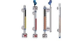
magnetic level gauge magnetic level indicator
Configurations of magnetic level gauges
Image courtesy Orion/Magnetrol
Fluid process control operations often involve vessel or tank storage of liquids. Continuous and accurate indication of the liquid level within the tank is an essential data point for process control decision making and safety. Several methods and instrument types are available for tank level measurement, each with its own set of attributes that may be advantageous for a particular installation. Selection criteria for a tank liquid level indicator may include:
  • Direct or indirect measurement of level
  • Level measurement accuracy and reliability
  • Tank shape, regular or irregular
  • Media compatibility with measurement device
  • Requirements for maintenance or calibration
  • Compatibility with process temperature and pressure range
  • Local display and visibility
  • Level indication signal type and transmission
  • Level alarm switches or other indicators
The selection of a magnetic level indicator, also referred to as a magnetic level gauge, for the project will likely be based upon at least one of the instrument's strengths. Magnetic level gauges have a host of potentially positive features for level indication.
  • Continuous level measurement
  • Operable without electric power
  • Direct visual tank fluid level indication, regardless of tank shape or profile.
  • Wide range of operating temperature and pressure
  • Breakage resistant construction
  • Range of construction materials available to accommodate corrosive media
  • Measuring indicators, switches, and transmitters mounted externally, without contacting the medium being measured.
  • Low maintenance operation.
  • Readable level indication from greater distance than glass sight gauges.
  • Applicable to large fluid level ranges with a single instrument.
Magnetic level indicators have a strong position in the tank liquid level measurement field and should be considered as a candidate for fulfilling those application requirements. There are many options available to customize the level indicator for each specific application. I have included a technical data sheet from Orion Instruments, a manufacturer of level instrumentation, for more detail. Share your application challenges with a sales engineer that specializes in level measurement. Combining your process knowledge with their product application expertise will yield positive solutions.


Magnetic Flowmeters: Principles and Applications

industrial process measurement instrument magnetic flow meter magmeter volumetric flow transmitter
Magnetic flowmeters are well suited for flow measurement
with conductive fluids.
Image courtesy Yokogawa
Fluid process control operations rely on the operator's ability to accurately determine qualities and quantities of liquid or gaseous materials. In terms of appraising and working with fluids (such as liquids, steam, and gases) the flowmeter is a staple tool, with the simple goal of expressing the delivery of a subject fluid in a quantified manner. Measurement of media flow velocity can be used, along with other inputs, to determine volumetric or mass flow. The magnetic flowmeter, also called a magmeter, is one of several technologies used to measure fluid flow.

In general, magnetic flowmeters are sturdy, reliable devices able to withstand hazardous environments while returning accurate measurements to operators of a wide variety of processes. The magnetic flowmeter has no moving parts. The operational principle of the device is powered by Faraday’s Law, a fundamental scientific principle stating that a voltage will be induced across any conductor moving at a right angle through a magnetic field, with the voltage being proportional to the velocity of the conductor. The principle allows for an inherently hard-to-measure quality of a substance to be expressed via the magmeter. In a magmeter application, the meter produces the magnetic field referred to in Faraday’s Law. The conductor is the fluid. The actual measurement of a magnetic flowmeter is the induced voltage corresponding to fluid velocity. This can be used to determine volumetric flow and mass flow when combined with other measurements.

The magnetic flowmeter technology is not impacted by temperature, pressure, or density of the subject fluid. It is however, necessary to fill the entire cross section of the pipe in order to derive useful volumetric flow measurements. Faraday’s Law relies on conductivity, so the fluid being measured has to be electrically conductive. Many hydrocarbons are not sufficiently conductive for a flow measurement using this method, nor are gases. On the other hand, water and aqueous solutions tend to exhibit sufficient conductivity to apply magmeter technology.

Magmeters apply Faraday’s law by using two charged magnetic coils; fluid passes through the magnetic field produced by the coils. A precise measurement of the voltage generated in the fluid will be proportional to fluid velocity. The relationship between voltage and flow is theoretically a linear expression, yet some outside factors may present barriers and complications in the interaction of the instrument with the subject fluid. These complications include a higher amount of voltage in the liquid being processed, and coupling issues between the signal circuit, power source, and/or connective leads of both an inductive and capacitive nature.

In addition to salient factors such as price, accuracy, ease of use, and the size-scale of the flowmeter in relation to the fluid system, there are multiple reasons why magmeters are the unit of choice for certain applications. They are resistant to corrosion, and can provide accurate measurement of dirty fluids – making them suitable for wastewater measurement. As mentioned, there are no moving parts in a magmeter, keeping maintenance to a minimum. Power requirements are also low. Instruments are available in a wide range of configurations, sizes, and construction materials to accommodate various process installation requirements.

As with all process measurement instruments, proper selection, configuration, and installation are the real keys to a successful project. Share your flow measurement challenges of all types with a process measurement specialist, combining your own process knowledge and experience with their product application expertise to develop an effective solution.

New Fluid System Connectors From Miller Energy

quick connect hose fittings for hydraulic and pneumatic systems
One of the many series of quick connect hose couplings
from Parker
Image courtesy of Parker Hannafin
Miller Energy now distributes the Parker line of fittings, couplings, quick connects, and hose products for commercial and industrial applications. The addition of this well known and respected brand to the company's product portfolio enables Miller Energy to serve a wider array of customer needs, as well as integrate the new products with its other process measurement and control products to deliver complete, ready to install, solutions for many applications.

An overview of the quick coupling products, just a part of the new product offering, is provided below. To find out more, contact Miller Energy directly and share your hydraulic, pneumatic, and fluid handling requirements and challenges. Leverage your own knowledge and experience with their product application expertise to develop effective solutions.


Miller Energy Expands Product Offering

general purpose solenoid valves for industrial use
Miller Energy is now a distributor of Asco solenoid
valves for a wide range of general and special applications
Miller Energy, through its acquisition of a New Jersey based distributor, has greatly expanded the company's offering of solenoid valves, pneumatic system components, and fluid handling and control components.

A solenoid is an electrical device, converting electrical energy input to a linear mechanical force. Solenoids are used to provide rapid two state mechanical movement of other devices. In process control applications, those devices are often fluid control valves.

At the basic level, a solenoid is an electromagnetic coil and a metallic rod or arm. Electrical current flow in the coil creates a magnetic field which will position the rod in one of two locations, depending upon whether the coil is energized. The movable component of the solenoid is linked to, or part of, the operating mechanism of another device. This allows the switched electrical output of a controller to regulate mechanical movement in another device and cause a change in its operation. A common solenoid application is the operation of small valves.

A plunger solenoid contains a movable ferrous rod, sometimes called a core, enclosed in a tube sealed to the valve body and extending through the center of the electromagnetic coil. When the solenoid is energized, the core moves to its equilibrium position in the magnetic field. The core is also a functional part of valve operation. It's repositioning causes a designed changed in the valve operating status (open or close). There are countless variants of solenoid operated valves exhibiting particular operating attributes designed for specific types of applications. In essence, though, they all rely on the electromechanical operating principle outlined here.

A solenoid valve is a combination of two functional units.
  • The solenoid (electromagnet) described above.
  • The valve body containing one or more openings, called ports, for inlet and outlet, and the valve interior operating components.
Flow through an orifice is controlled by the movement of the rod or core. The core is enclosed in a tube sealed to the valve body, providing a leak tight assembly. A controller energizing or de-energizing the coil will cause the valve to change operating state between open and closed, regulating fluid flow. There are almost countless variants of solenoid operated valves, specifically tailored for applications throughout industrial, commercial, and institutional operations.

The document provided below illustrates a portion of the broad array of solenoid valves available for industrial control applications. Share your fluid control requirements and challenges with an application specialist. Leverage your process knowledge and experience with their product application expertise to produce effective solutions.


Bulb and Capillary Temperature Switches

general purpose industrial temperature pressure vacuum switch
General purpose temperature switch with bottom connection
for capillary and bulb specific for each application.
Image courtesy United Electric Controls
Not all processes or operations require the use of state of the art technology to get the desired results. Part of good process design is matching up the most appropriate methods and technology to the operation.

One method of changing the state of a switch in response to a process temperature change is a bulb and capillary temperature switch. The switch operation produces a state change in the mechanical switch when the temperature of a process control operation crosses a certain threshold. Bulb and capillary switches have the advantage of operating without electricity, simplifying their application.

The physical operating principle behind the capillary thermostat relies on the use of a fluid. The fluid inside the thermostat expands or contracts in response to the temperature at the sensing bulb. The change in fluid volume produces a force upon a diaphragm or other mechanical transfer device. The diaphragm is connected to, and changes the status of, an adjoining circuit using a snap action switch. For example, a main use of the operating principle in action is when a commercial food company relies on the capillary switch to control temperature related to processing and distribution. Each individual use of a bulb and capillary thermostat is specifically designed based on manufacturer and industry specifications, all of which apply the same physical principle of fluid based physics.

Because of their simplicity and comparatively modest cost, commercial versions of bulb and capillary switches find application throughout residential and commercial settings. Some common applications include warming ovens, deep fat fryers, and water heaters. The HVAC industry uses capillary and bulb switches because the rate of temperature change found in their applications fits the adjoining range offered by the bulb and capillary type switches. Operation of the temperature switches is subject to a few limitations. The switching point is often fixed, so the application must be without a requirement for an adjustable setpoint. The temperature range over which the switches are suitable is comparatively limited, with a matching of the bulb and capillary fluid system to the application temperature range a necessary task in product selection. Within its proper sphere of use, though, bulb and capillary temperature switches offer simple, reliable operation, with little requirement for maintenance.

Bulb and capillary switches are typically used to evaluate average temperature and are especially useful for applications where the temperature is to be maintained at a well-known, consistent value. The bulb portion can be configured to accommodate mounting within the media to be controlled. The devices can be applied effectively to liquid and gaseous media when the proper bulb is used.

Industrial versions of bulb and capillary switches are fitted with appropriate housings for the installation environment. Hazardous location installation can be accommodated, as well as high current ratings and auxiliary functions. There are almost countless variants of bulb and capillary temperature switches available. Don’t overlook these simple mechanical devices as candidates for application in any temperature control process. Share your application requirements and challenges with product specialists for useful recommendations.