Showing posts with label Eastern Pennsylvania. Show all posts

Paperless + Wireless Process Control Recorder

Paperless and Wireless Process Control Recorder
Paperless and Wireless
Yokogawa GX20W
There are probably few among us who long for the days when process recorders used paper. Video based graphic (also known as paperless) recorders, aside from being paperless, provide a broad range of functionality that empowers a user to display and deliver process information in whatever way is most useful for the application.

High sampling speed of multiple inputs that can be configured to accommodate a range of input signals, along with data storage, network communications and programmable alarm outputs power up the usefulness of these instruments for monitoring and documenting process operation. Many utilize touch sensitive screens, eliminating any buttons or keys on the operator panel.

Some of the great features available on today's paperless recorders:

  • Multiple channels of input
  • Start/stop recording by batch, and create data files
  • Ample internal memory
  • Creation of template-based Excel spreadsheets
  • Custom display function
  • Historical data with date and time calendar search function
  • Ethernet interface
  • PROFIBUS-DP and EtherNet/IP protocols
  • Dust and splash-proof front panel
  • Front panel door lock and login function

Wireless Seals the Deal

Wireless technology is a serious contributor in the effort to improve plant efficiency, lower risk, and increase productivity. Wireless recorders are now available for monitoring virtual all process variables such as pressure, temperature, level, and flow (plus many more).  The use of wireless recorders provides a compelling argument when you consider installation cost savings and convenience.  Savings estimates as high as 70% are realized when compared to the cost using cables for the same application.

There are many options and variants to accommodate every conceivable process control application. Share your data acquisition and process monitoring challenges with instrumentation specialists, leveraging your own knowledge and experience with their product application expertise to develop an effective solution.

For more information on paperless recorders, contact Miller Energy by visiting https://millerenergy.com or calling 908-755-6700 in NJ or 610-363-6200 in PA.

Pressure Switches - The Stalwart of Pressure Instrumentation

pressure switch
Pressure switch in an
explosion-proof housing.
(United Electric)
A pressure switch is an electromechanical device that detects the presence of fluid pressure and responds by opening or closing an electrical or pneumatic circuit.

In heavy industry, pressure switches are used in virtually every power plant, refinery, chemical plant, paper mill, steel mill, or other manufacturing plant that blends ingredients.

Pressure switches are simple devices. They can be broken down to their major parts: a pressure port or connection; a sensor that moves in relationship to changing pressures; an electrical or pneumatic switch that opens or closes upon movement; and finally a housing that protect the internals of the pressure switch from the ambient conditions.

pressure switch
Differential pressure switch.
(United Electric)
Pressure switches use a variety of sensing elements such as diaphragms, bellows, bourdon tubes, or pistons. In most cases, the movement of these sensors, caused by pressure fluctuation, is transferred to a set of electrical contacts to open or close a circuit. Normal status of a switch is the resting state. A pressure switch will be in its “normal” status when it senses low or minimum pressure. For a pressure switch, “normal” status is any fluid pressure below the trip threshold of the switch.

One of the earliest and most common designs of pressure switch was the bourdon tube pressure sensor accompanied by a mercury switch. A mercury switch is a position sensitive glass bulb containing mercury that flows over, or away from, the electrical contacts. When pressure is applied, the bourdon tube attempts to straighten, and moves enough to slightly tilt the mercury switch. Many of these kind of pressure switches were sold on steam boilers, and while they became a de facto standard, they were sensitive to vibration and breakage of the mercury bulb.

electrical switch contacts
NO vs. NC electrical switch contacts.
The most common electrical switch used in pressure switches are "microswitch" type. These are also called "snap switches" because they are actuated by very little physical force, through the use of a tipping-point mechanism. These type of switches offer reliability and repeatability. They also are available in many different voltages and current ratings

One of the criteria of any pressure switch is the deadband or (reset pressure differential). This setting determines the amount of pressure change required to reset the switch to its normal state after it has tripped.  The “differential” pressure of a pressure switch should not to be confused with differential pressure switch, which actually measures the difference in pressure between two separate pressure ports.

When selecting pressure switches you must consider the electrical requirements (volts, amps, AC or DC), the area classification (hazardous, non-hazardous, general purpose, water-tight), pressure sensing range, body materials that will be exposed to ambient contaminants, and wetted materials (parts that are exposed to the process media).

It's always a good idea to discuss your application with an expert before specifying or installing a pressure switch. You'll end up saving time and money, and ensure long, safe operation.

For more information on pressure switches, contact Miller Energy by visiting https://millerenergy.com or by calling one of these numbers: In New Jersey 908-755-6700. In Pennsylvania 610-363-6200.

Miller Energy - Industrial Instrumentation & Process Control Equipment

Miller Energy is a Manufacturer's Representative and Distributor of Industrial Instrumentation and Process Control Equipment. Since 1958, we have been committed to exceeding our customers expectations by providing an unparalleled level of customer service and local technical support. We offer the most comprehensive line of measurement, control, and communication solutions in the Industry today. The products we represent solve challenging applications in the Industrial Gas, Power, Refining, Chemical / Petro-Chemical, Food & Beverage, Water/Wastewater, and Pharmaceutical markets.

NJ 908-755-6700 
PA 610-363-6200

Bimetal Thermometers for Industrial Process Measurement

stainless steel bimetal thermometer
Bimetal thermometers have a place in modern process
measurement systems.
Image courtesy Wika
Temperature measurement is everywhere, with broad ranges of accuracy, range and other operational requirements to bring the measurement data into a process management or control system. The process could be as simple as measuring a cooking temperature, or a part of a complex refining operation. Temperature provides an indication of heat energy level that is used in many ways throughout process control.

Though there are many instruments and technologies available to measure temperature, one that everyone is familiar with is the dial thermometer. A familiar numeric scale and a pointer indicate the temperature at the sensing location. Even within the product range of dial thermometers, there are several differing methods utilized to produce a temperature reading. One of these is the bimetal thermometer.

A bimetallic thermometer is named for the mechanism that responds to process temperature and provides the force to position the indicator needle over the scale on the dial face. A bimetal is formed from two dissimilar metals bonded together. The metals expand and contract at different rates in response to a change in their temperature. A bimetal thermometer relies on the predictable deformation of a bimetal spring or strip in response to a temperature change. The mechanical deformation is transformed into rotational movement of the indicating needle on the instrument face where the corresponding temperature can be read by a technician or operator. This design principle has been in use throughout laboratories, kitchens, and industry for many years and has proven to be predictably accurate, stable, and rugged.

The major advantages of the bimetallic thermometer are its relative cost, ease of use, and ability to function without any external power source. This class of instruments provides operability up to +1000°F.

When applying dial faced thermometers, there are several main considerations.

  • Scale - The display behind the indicating pointer. The scale divisions impact the instrument's accuracy at indicating process temperature.  
  • Range - The physical suitability of the instrument to be exposed to the temperatures which may be present in the process. May be the same as scale.
  • Dial Size - Larger diameter dial faces make reading the instrument indications easier.
  • Connection - There are numerous options for the way in which the probe or stem, which is inserted into the process, attaches to the dial portion or head of the instrument. Common arrangements are back, side, or bottom connected. If the head cannot be rotated or angled, the connection attributes may be the sole determinant of how the dial face is oriented.
  • Stem Length - The stem extends from the head into the process. Coordinating the stem length with the insertion depth into the process and the placement of the instrument is important to achieving a useful and ergonomic installation.
  • Materials of Construction - Make sure the selected instrument is rugged enough to withstand expected environmental conditions at the installation site.
These are only the primary considerations. Share your operational requirements with a product specialist. Leverage your own knowledge and experience with their product application expertise to develop the optimal solution.

Guided Wave Radar - An Option for Level Measurement in Hygienic Applications

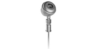
GUIDED WAVE RADAR LEVEL TRANSMITTER FOR HYGIENIC APPLICATIONS
A special version of the Magnetrol Eclipse 705
is configured for hygienic applications.
Image courtesy Magnetrol
Measurements of a variety of process conditions are utilized to monitor and control operations and output. One general goal of measurement, other than answering the question "how much", is to avoid or minimize any interference with the process itself. A second goal is to not be fooled by the process into returning a false measurement result.

Guided wave radar is based upon the principle of TDR (time domain reflectometry). Pulses of electromagnetic energy travel from the emitting antenna via a fixed waveguide or probe immersed in the target medium. When it contacts the media surface, the pulse energy is reflected back along the probe to a receiving antenna. The instrument actually measures the time elapsed between the pulse transmission and the detection of the reflected return. The time measurement is used to calculate the distance from the antenna to the media surface. The distance calculation, with knowledge of the vessel, can be converted into a value indicating media level or volume. Of course, this is a simplified account of the operating principal.

Guided wave radar (GWR), as opposed to an open style radar level measurement method, uses a probe immersed in the process media to guide high-frequency electromagnetic waves into the media being measured. While it does involve contact by the sensing instrument with the media, GWR eliminates interference from fixtures or structures that may exist within the tank or vessel. The immersion probe waveguide also attenuates the impact of media turbulence and other potential disturbances. The waveguide reduces the potential impact of elements that may adversely impact the measurement accuracy, resulting in greater accuracy and reliability of the measurements.

For hygienic applications, the transmitters are available with 304 stainless steel housings designed specifically for use in facilities with the special requirements for the wetted and non-wetted materials, process connections and surface finishes of hygienic industries. In addition to high accuracy, the GWR instrument output is not impacted by media buildup on the sensing probe.

Share your level measurement challenges with process instrumentation specialists. Leverage your own process knowledge and experience with their product application expertise to develop an effective solution.


Mass Flow Controllers for Precise Dosing

mass flow controller cutaway view
Mass Flow Controller - Cutaway View
Image courtesy Brooks Instrument 
There are processing applications that require very accurate flow or dosing control of added constituents. The applications are diverse, ranging from controlled gas flow to precise metering of product fluid components. The ability to accurately and reliably measure and regulate mass flow of a fluid into a process is a common task in process measurement and control.

Thermal mass flow measurement, in basic operation, infers mass flow by measuring the heat dissipation from a heated temperature sensor and comparing it to an unheated reference temperature sensor. The heat dissipation is directly proportional to the mass flow of gas or liquid.

Thermal mass flow meters are very popular for several reasons. They have no moving parts, have a fairly unobstructed flow path, are accurate over a wide range of flow rates, calculate mass flow rather than volume, measure flow in large or small piping systems, and do not need temperature or pressure compensation.

For a process control application, accuracy and real time delivery of measurement data are key factors. Advanced smart controls with a range of communications options that will interface with a variety of devices across a choice of platforms bring high levels of functionality and ease of use to an application. For gas applications, smart technology allows one device to be applied to multiple gas types and ranges without removing the flow meter from the system. Product selection is enhanced by the availability of instruments targeted at a range of applications.

Share your flow measurement and control challenges with process measurement and control specialists. Leverage your own process knowledge and experience with their product application expertise to develop effective solutions.

Innovative Non-Contact Radar Liquid Level Transmitter

non-contact radar level transmitter for industrail process control
Pulsar R86 non-contact radar level transmitter.
Image courtesy Magnetrol
Level measurement of liquids and solids in containers, silos, tanks and other vessels is an essential part of many processing operations. Accurate and reliable measurement of solids or liquid level contributes to operational success, as well as enhancing safety, both of which contribute to the bottom line and successful operation.

Magnetrol, globally recognized innovator in flow and level measurement, incorporates years of experience into their latest version of non-contact radar level measuring instruments. The incremental improvements contribute to easier, more flexible installation and better performance.

The R86 is a 26 GHz level transmitter applicable across a wide range of requirements in many industries. Benefits of the 26 GHz radar signal, with its smaller wavelength, are a smaller antenna and improved 1mm resolution. The narrower beam from the antenna makes positioning the transmitter less restrictive, with easier accommodation for vessel fixtures or geometry. Advanced on board diagnostics supplement the improved performance and deliver the information needed to maintain proper operation and process visualization. A broad range of antennas and mountings are available for the R86, accommodating various tank sizes, fittings, and temperatures

More information on the Pulsar R86 is provided in the brochure included below. Share your level measurement challenges and requirements with a process measurement specialist. Employ the leverage of their product application expertise to your own process knowledge and experience to develop an effective solution.


Using Brooks Mass Flow Controllers with LabVIEW™

coriolis mass flow controller
Coriolis mass flow controller
Image courtesy Brooks Instrument
Brooks Instrument is the manufacturer of highly accurate and repeatable mass flow controllers. LabVIEW™ develops integrated software for building measurement and control systems used in laboratories, universities, and pilot manufacturing plants. The combination of Brooks MFCs and LabVIEW software provides users a great option for measurment, control, data acquisition and data storage for mass flow.

Listed below are some of the more convenient communication methods to tie Brooks MFCs and LabVIEW™ software together.

Analog Signal Interface

In many situations LabVIEW™ software users also use analog to digital
I/O cards. With analog input cards, users can run their mass flow controllers utilizing a standard 0-5 volt or 4-20 mA analog signaling via LabVIEW™. This is a time-tested, traditional approach and is recommended for applications without the availability of digital control systems.

RS485 Digital Interface

Brooks Instrument mass flow devices configured with RS485 communications (must have the ‘S’ communications option) provide RS485 digital communications via a 15-pin D connector. The RS485 digital signal is passed directly to a computer running LabVIEW™ through a serial RS485 converter. Brooks models GF40, GF80 and SLA Series mass flow controllers are available with the ‘S’ communications option.

Its valuable to note that there is also a free set of VI file for use with LabVIEW from Brooks. These can be loaded directly into the LabVIEW™ application and provide the basics required to create a LabVIEW control interface using the S-Protocol digital command structure. The VI files are available for download from the Brooks Instrument website.

Another communications alternative is using Brook’s Smart DDE (Dynamic Data Exchange) software tool to create links between the LabVIEW™ application and the GF40, GF80 or SLA Series flow, control, and configuration parameters. Additionally, the user can leverage Windows applications (Excel, Word, Access) and programming languages ( C++, C#, Visual Basic) and SCADA programs from suppliers such as Allesco and Millennium Systems International. No knowledge of the mass flow device S-Protocol command structure is required. With Smart DDE, the user gets direct access to the required data fields. While not a complete turnkey option, it greatly reduces the amount of code required to communicate between LabVIEW and the mass flow controller.

DeviceNet Digital Signal Interface

Brooks models GF40, GF80 and SLA, configured for DeviceNet digital communications, can also be controlled via the LabVIEW™ application provided a National Instruments DeviceNet interface card, associated drivers, and software are used. These additional items support the development of application interfaces using LabVIEW™ software for Windows and LabVIEW™ Real-Time.

According to the National Instruments website:
National Instruments DeviceNet for Control interfaces are for applications that manage and control other DeviceNet devices on the network. These interfaces, offered in one-port versions for PCI and PXI, provide full master (scanner) functionality to DeviceNet networks. All NI DeviceNet interfaces include the NI-Industrial Communications for DeviceNet driver software, which features easy access to device data and streamlined explicit messaging. Use a real-time controller such as PXI and NI industrial controllers to create deterministic control applications with the NI LabVIEW Real-Time Module.

Share your mass flow measurement and control challenges with application experts, leveraging your own knowledge and experience with their product application expertise.

Fixed Gas Detectors

fixed installation gas detector sensor transmitter
Fixed installation gas sensor / transmitters.
Image courtesy 3M - Oldham
The expansion of demand for increased levels of safety in the workplace continues, with calls for better protection for workers, the plant, the environment, and surrounding communities all weighing on operators to look for ways to reduce risk. Industrial plants, especially those employing hazardous or flammable materials, can have very high risk levels. Reducing the probability of accident or failure can bring a very substantial benefit for long term operation.

Oldham, a 3M brand, manufactures fixed and portable hazardous gas detection and monitoring equipment for application in commercial and industrial settings. Their sensors and stations enable continuous monitoring of process or facility conditions and alert of potentially dangerous conditions. The application possibilities range through every industry.

The product line employs a number of technologies, with varied housings and form factors to accommodate any installation requirement. A wide range of gases can be detected and measured. Share your hazardous gas and flame detection monitoring challenges with process measurement specialists, leveraging your own knowledge and experience with their product application expertise to develop a safer solution for your facility.

Smart Output™ Module For Water System Monitoring

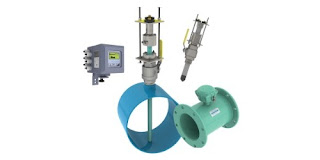
magnetic flowmeter variants
Full bore flanged and insertion style magnetic flowmeters,
with Smart Output™ technology to enhance their functionality.
Image courtesy McCrometer 
Water distribution systems, though mostly invisible to the general public, are highly complex infrastructure arrangements that extend to a very large number of locations throughout a service area. Monitoring the activity and operational health of the distribution system, key to maintaining high levels of efficiency and service, requires measurement instrumentation installed throughout the system.

Magnetic flowmeters are an integral part of water system instrumentation. Their advantages for use in water systems were outlined in a previous article on how magnetic flowmeters work. McCrometer is an innovator in the design and manufacture of magnetic flowmeters for water system flow measurement. Their Smart Output™ technology is available for use with full bore flanged and insertion style flowmeters to provide the information needed for modern water system operation.

  • AC or DC powered versions
  • Compatible with Sensus and Itron smart water networks
  • Enables networking of water meters throughout distribution system
  • Queries, diagnostics, and data transfer can be scheduled or on demand
  • Enables AMR (Automatic Meter Reading) and AMI (Advanced Metering Infrastructure)
The Smart Output™ function is an additional module included as part of the instrument transmitter. 

More information is available from product application specialists, with whom you should share your flow measurement challenges of all types. Leverage your own process knowledge and experience with their product application expertise to develop effective solutions.

Best Temperature Control Performance Starts With a Match of Sensor Configuration to Application

temperature sensors configured for surface temperature measurement
A specially configured temperature sensor can improve
measurement response and process control.
Image courtesy Applied Sensor Technologies
There are more temperature controlled operations than any of us could count in a lifetime, each with a set of signature performance requirements and design challenges. Matching the means of temperature measurement, the control loop characteristics, and heat delivery method to the application are essential to achieving successful operation.

Step one is to measure the process temperature. This sounds simple until you start researching products and technologies for measuring temperature. Like the temperature controlled operations mentioned previously, they are numerous. To filter the possible candidates for temperature sensing devices, consider these aspects of your application and how well a particular sensor may fulfill your requirement.
  • Response Time - How rapidly the sensor will detect a change in process temperature is a function of how the sensor is constructed and how it is installed. Most temperature sensors are enclosed or encapsulated to provide protection for the somewhat vulnerable sensing element. Greater mass surrounding the sensing element, or a shape that inhibits heat transfer from the process to the sensor, will slow sensor response. Whether the slower response time will adversely impact process operation needs to be considered. More consideration is due to the manner in which the temperature sensor assembly is installed. Not all applications involve a fluid in which the sensor assembly can be conveniently immersed, and even these applications benefit from careful sensor placement.
  • Accuracy - Know what your process needs to be effective. Greater levels of accuracy will generally cost more, possibly require more care and attention to assure the accuracy is maintained. Accuracy is mostly related to the type of sensor, be it RTD, thermocouple, or another type.
  • Sensitivity - Related to the construction, installation, and type of sensor, think of sensitivity as the smallest step change in process temperature that the sensor will reliably report. The needs of the process should dictate the level of sensitivity specified for the temperature sensor assembly.
Take a simple application as an illustration. Heat tracing of piping systems is a common function throughout commercial and industrial settings experiencing periods of cold weather. Electric heat trace installations benefit from having some sort of control over the energy input. This control prevents excessive heating of the piping or applying heat when none is required, a substantial energy saving effort. A temperature sensor can be installed beneath the piping's insulation layer, strapped to the pipe outer surface. A specially designed sensor assembly can improve the performance of the sensor and the entire heat trace control system by enhancing the response time of the temperature sensor. A right angled sheath permits insertion of the sensor beneath the piping insulation while orienting the connection head upright. A surface pad at the tip of the sheath increases the surface contact with the pipe to provide faster sensor response. The surface pad is a metal fixture welded to the sensing end of the temperature sensor assembly. It can be flat, for surface temperature measurements, or angled for installation on a curved surface, like a pipe. The increased surface contact achieved with the surface pad promotes the conduction of heat to the sensor element from the heated pipe in our illustration. This serves to reduce and improve the response time of the sensor. Adding some thermally conductive paste between the pad and the pipe surface can further enhance the performance. While the illustration is simple, the concepts apply across a broad range of potential applications that do not allow immersion of the temperature assembly in a fluid.

A simple modification or addition of an option to a standard sensor assembly can deliver substantially improved measurement results in many cases. Share your temperature measurement requirements and challenges with a process measurement specialist. Leverage your own process knowledge and experience with their product application expertise.

Maintenance Procedures - Yokogawa ADMAG TI Series AXW Magnetic Flowmeter

magnetic flow meter with corrosion resistant lining
The AXW series of magnetic flow meters is available in
a range of sizes with corrosion resistant lining.
Image courtesy Yokogawa
The ADMAG AXW™ series of magnetic flow meters has been developed based on Yokogawa's decades of experience in the design and manufacture of magnetic flowmeters. The AXW series continues the tradition of high quality and reliability that has become synonymous with the Yokogawa name.

The AXW series is ideal for industrial process lines, and water supply and sewage applications. With outstanding reliability and ease of operation, developed on decades of field-proven experience, the AXW will increase user benefits while reducing total cost of ownership.

Magnetic flow meters, also called electromagnetic flow meters or "magmeters", operate on a very simple principal. An electrically conductive liquid moving through a magnetic field will generate a voltage that is related to the velocity of the liquid. Magnetic flow meters have no moving parts and present little to no pressure drop to the piping system into which they are installed.

Sizes are available from 500 to 1800 mm (20 to 72 inch.) with a wide liner selection such as PTFE, natural hard rubber, natural soft rubber, and polyurethane rubber. The line accommodates industry standard process connections such as ASME, AWWA, EN, JIS, and AS flange standards. A submersible version is also available.

Care and maintenance for magnetic flow measurement devices is simple and minimal. The manual included below provides basic guidelines for maintenance procedures of ADMAG TI (Total Insight) Series AXW magnetic flowmeters. Share your flow measurement challenges with process instrument specialists, leveraging your own knowledge and experience with their product application expertise.


Top End Guided Wave Radar Level Transmitter

guided wave radar level transmitter
Magnetrol's model 706 embodies the best of guided
wave radar level measurement.
Image courtesy of Magnetrol
The Eclipse Model 706 is Magnetrol's loop powered high performance guided wave radar level transmitter. It incorporates many of the company's latest innovations into a single instrument capable of meeting the demanding requirements of an array of industrial applications.

Product improvements include increased signal to noise ratio, suitability for use with low dielectric media, and the ability to deliver accurate indication under foaming, flashing, or other challenging conditions. An extended probe offering enables use in measuring interface, liquified gas, even bulk solids.

The instrument is suitable for overfill applications, and does not use algorithms to infer measurements in a dead zone that may occur near the top of the probe in some other designs. The Eclipse 706 delivers true measurement right up to the process flange. Upgraded electronics allow the unit to be pre-configured prior to shipment, if requested. Additionally, the widest range of communications options is available.

For more information, share your level measurement challenges with a process measurement specialist. Leverage your own process knowledge and experience with their product application expertise to develop effective solutions.


Miller Energy Expands Capabilities With New Valve Line

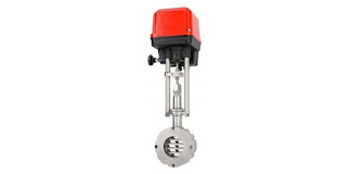
sliding gate valve with actuator
The sliding gate control valve is part of the Schubert & Salzer
product line. Image courtesy Schubert & Salzer.
Miller Energy is pleased to now represent, in the company's Pennsylvania office, Schubert & Salzer, a recognized innovator and manufacturer of high precision process flow control valves.

Schubert & Salzer specializes in precise control and stop valves for industrial fluid processing operations.
  • Sliding gate valves
  • Ball Sector Valves
  • Segment disc valves and segment disc orifices
  • Seat valves
  • Three-way valves
  • Sanitary valves
  • Pinch Valves
  • Manual valves
  • Positioners & controllers
  • Accessories to complement all products
With the expansion of its already wide range of common and specialized valve technologies, Miller Energy further solidifies its position as the go-to source for solutions to fluid process control challenges. Contact the Pennsylvania office for detailed product information. Share your challenges and leverage your process knowledge and experience with their product application expertise to develop effective solutions.


Magnetic Level Indicators

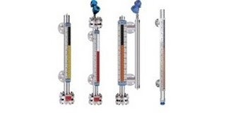
magnetic level gauge magnetic level indicator
Configurations of magnetic level gauges
Image courtesy Orion/Magnetrol
Fluid process control operations often involve vessel or tank storage of liquids. Continuous and accurate indication of the liquid level within the tank is an essential data point for process control decision making and safety. Several methods and instrument types are available for tank level measurement, each with its own set of attributes that may be advantageous for a particular installation. Selection criteria for a tank liquid level indicator may include:
  • Direct or indirect measurement of level
  • Level measurement accuracy and reliability
  • Tank shape, regular or irregular
  • Media compatibility with measurement device
  • Requirements for maintenance or calibration
  • Compatibility with process temperature and pressure range
  • Local display and visibility
  • Level indication signal type and transmission
  • Level alarm switches or other indicators
The selection of a magnetic level indicator, also referred to as a magnetic level gauge, for the project will likely be based upon at least one of the instrument's strengths. Magnetic level gauges have a host of potentially positive features for level indication.
  • Continuous level measurement
  • Operable without electric power
  • Direct visual tank fluid level indication, regardless of tank shape or profile.
  • Wide range of operating temperature and pressure
  • Breakage resistant construction
  • Range of construction materials available to accommodate corrosive media
  • Measuring indicators, switches, and transmitters mounted externally, without contacting the medium being measured.
  • Low maintenance operation.
  • Readable level indication from greater distance than glass sight gauges.
  • Applicable to large fluid level ranges with a single instrument.
Magnetic level indicators have a strong position in the tank liquid level measurement field and should be considered as a candidate for fulfilling those application requirements. There are many options available to customize the level indicator for each specific application. I have included a technical data sheet from Orion Instruments, a manufacturer of level instrumentation, for more detail. Share your application challenges with a sales engineer that specializes in level measurement. Combining your process knowledge with their product application expertise will yield positive solutions.


Bulb and Capillary Temperature Switches

general purpose industrial temperature pressure vacuum switch
General purpose temperature switch with bottom connection
for capillary and bulb specific for each application.
Image courtesy United Electric Controls
Not all processes or operations require the use of state of the art technology to get the desired results. Part of good process design is matching up the most appropriate methods and technology to the operation.

One method of changing the state of a switch in response to a process temperature change is a bulb and capillary temperature switch. The switch operation produces a state change in the mechanical switch when the temperature of a process control operation crosses a certain threshold. Bulb and capillary switches have the advantage of operating without electricity, simplifying their application.

The physical operating principle behind the capillary thermostat relies on the use of a fluid. The fluid inside the thermostat expands or contracts in response to the temperature at the sensing bulb. The change in fluid volume produces a force upon a diaphragm or other mechanical transfer device. The diaphragm is connected to, and changes the status of, an adjoining circuit using a snap action switch. For example, a main use of the operating principle in action is when a commercial food company relies on the capillary switch to control temperature related to processing and distribution. Each individual use of a bulb and capillary thermostat is specifically designed based on manufacturer and industry specifications, all of which apply the same physical principle of fluid based physics.

Because of their simplicity and comparatively modest cost, commercial versions of bulb and capillary switches find application throughout residential and commercial settings. Some common applications include warming ovens, deep fat fryers, and water heaters. The HVAC industry uses capillary and bulb switches because the rate of temperature change found in their applications fits the adjoining range offered by the bulb and capillary type switches. Operation of the temperature switches is subject to a few limitations. The switching point is often fixed, so the application must be without a requirement for an adjustable setpoint. The temperature range over which the switches are suitable is comparatively limited, with a matching of the bulb and capillary fluid system to the application temperature range a necessary task in product selection. Within its proper sphere of use, though, bulb and capillary temperature switches offer simple, reliable operation, with little requirement for maintenance.

Bulb and capillary switches are typically used to evaluate average temperature and are especially useful for applications where the temperature is to be maintained at a well-known, consistent value. The bulb portion can be configured to accommodate mounting within the media to be controlled. The devices can be applied effectively to liquid and gaseous media when the proper bulb is used.

Industrial versions of bulb and capillary switches are fitted with appropriate housings for the installation environment. Hazardous location installation can be accommodated, as well as high current ratings and auxiliary functions. There are almost countless variants of bulb and capillary temperature switches available. Don’t overlook these simple mechanical devices as candidates for application in any temperature control process. Share your application requirements and challenges with product specialists for useful recommendations.


Application of Load Cells in Process Measurement

Advanced force, weight instrument for load cells
The advanced model G5 can handle input signals from multiple load cells
Image courtesy of BLH Nobel
In industrial application of process measurement and control, principles of the physical sciences are combined with technology and engineering to create devices essential to modern high speed, high accuracy system operation. Years of research, development, and the forward march of humanity’s quest for scientific knowledge and understanding yields packaged devices for process measurement that are easily applied by system designer and operators.

Load cells are the key components applied to weighing component or processed materials in modern industrial operations. Load cells are utilized throughout many industries related to process management, or just simple weighing operations. In application, a load cell can be adapted for measurement of items from the very small to the very large.

In essence, a load cell is a measurement tool which functions as a transducer, predictably converting force into a unit of measurable electrical output. While many types of load cells are available, one popular cell in multiple industries is a strain gauge based cell. Strain gauge cells typically function with an accuracy range between 0.03% and 0.25%. Pneumatically based load cells are ideal for situations requiring intrinsic safety and optimal hygiene. For locations without a power grid, there are even hydraulic load cells, which function without need for a power supply. These different types of load cells follow the same principle of operation: a force acts upon the cell (typically the weight of material or an object) which is then returned as a value. Processing the value yields an indication of weight in engineering units.

For strain gauge cells, deformation is the applied operational principal, where extremely small amounts of deformation, directly related to the stress or strain being applied to the cell, are output as an electrical signal with value proportional to the load applied to the cell. The operating principle allows for development of devices delivering accurate, precise measurements of a wide range of industrial products.

Load cell advantages include their longevity, accuracy, and adaptability to many applications, all of which contribute to their usefulness in so many industries and applications. A common place to find a strain gauge load cell in use is off a causeway on a major highway at a truck weigh station. Through innovation, load cells have been incorporated in an efficient measuring system able to weigh trucks passing through the station, without having each stop. Aircraft can be weighed on platform scales which utilize load cells, and even trains can be weighed by taking advantage of the robust and dependable nature of the transducers.

Thanks to their widespread incorporation and the sequential evolution of technology, load cells are a fantastically useful tool in process measurement and control. Share your process weighing challenges with application experts, combining your own process expertise with their product knowledge to develop an effective solution.

Electronic to Pneumatic Converter

illustration of setup for current to pneumatic converter
Component schematic using electronic controller and pneumatic
control valve
Image courtesy of Yokogawa
A straight forward device, the current to pneumatic converter produces a pneumatic output signal that is proportional to an electrical control level input signal of 4 to 20 mA or 10 to 50 mA. This provides a useful interface between electronic controllers and pneumatically operated valves, air cylinders, or other air operated control elements.

Pneumatic signals are regularly used throughout many installations as matter of safety, legacy, or because a pneumatic signal can provide motive power to an operating device such as a valve positioner. Electrical control signals can be transmitted long distances across wires to deliver control signals to operating elements. The current to pneumatic converter provides a bridge between the two systems and allows the most beneficial aspects of each to be brought to bear on process operation.

Converters are available in standard variants that accommodate a number of hazardous location designations, as well as several output pressure ranges and calibrations. Share your process control connectivity challenges with application specialists, combining your own process knowledge and experience with their product application expertise to develop effective solutions.


WirelessHART Toxic and Combustible Gas Detector

wirelessHART toxic and combustible gas detector
Vanguard WirelessHART toxic and combustible
gas detector for industrial safety use.
Image courtesy United Electric Controls
Earlier this year, United Electric Controls released its Vanguard WirelessHART gas detector for use in a wide range of industrial settings. Detecting potentially hazardous levels of toxic or combustible gases is an essential element of plant safety where these gases are employed. The Vanguard detector integrates seamlessly into existing WirelessHART networks and asset management systems. A battery lifespan of 5 years and a design that provides in-place test and calibration mean there will be little burden to maintaining the proper operation of the unit.

More detail is provided in the brochure included below. The Vanguard incorporates solid construction and design features to deliver ease of use and long service life. Share your gas detection and process measurement challenges with instrumentation specialists. Combining your own process experience and knowledge with their product application expertise will result in an effective solution.


Level and Flow Instruments for Hygienic Applications

Magnetrol is a globally recognized leader in the manufacture of flow and level instrumentation for industrial scale applications. The products employ a range of differing technologies to provide measurement precision across an array of challenging applications. The informational piece included below highlights Magnetrol's products intended for use in industries, such as pharma or food processing, where special materials and product design are employed to meet the special requirements of hygienic processing.

Share your flow and level measurement challenges with process instrumentation experts, combining your own knowledge and experience with their expertise to develop effective solutions.