Showing posts with label flow measurement. Show all posts

Selecting Variable Area Flow Meters for Process Flow Measurement

Variable Area Flow Meters

Many industrial processes involve the movement of fluid product components, either liquid or gaseous, through pipes. Because processing is about control, an input to the facility's management, measurement, or data logging centers will answer the query, "How much is going through that pipe?" 

In the industrial process measurement and control industry, there are several ways for quantifying flow, each with unique characteristics that may be useful under certain operating situations. All flow measuring methods are indirect because the actual measurement is of a character influenced predictably by a change in the media flow. Flow measurement is a critical component that, when paired with other fluid properties, is used to calculate the total mass of a fluid passing through the measurement site. 

The variable area meter, commonly known as a rotameter and VA meter, is a tried and true flow measuring device that operates by creating an equilibrium between an upward force created by fluid motion and a downward force, gravity. A tapering glass or metal tube encases a specifically shaped float, also known as a shaped weight, in the device. VA meters must be positioned vertically, with the media flowing upward from the bottom, so that the gravity force required for functioning is correctly aligned with the flow direction. As fluid flows upward via the precisely tapered tube, drag is created on the float enclosed within the tube, pulling it upward. As the float rises, the open space between the float and the tube wall expands, causing the fluid velocity and drag force to decrease. The flow velocity within the tube will cause the weight to climb for any given flow volume until the drag force generated by the flow reaches equilibrium with the countervailing power of gravity on the float. The tube and float are well designed, allowing for an immediate indication of flow volume.

Variable area flowmeters have the following operating characteristics: 

  • There is no need for external power or fuel for functioning. 
  • Vertical installation is required, with flow arriving at the bottom. 
  • Meters are calibrated to a given chemical and temperature. 
  • The operation is stable and has a modest pressure drop. 
  • For operation, constant gravity is required. 
  • Flow rate can be read locally using a meter or a scale inscribed on the tube. 
  • The visibility of the float through the medium is required for unit flow readings using glass tubes. 
  • For industrial flow metering equipment, accuracy is relatively low. 
  • Inexpensive upkeep, simple construction, and low comparative cost.

Brooks Instrument, a world-renowned maker of flow, pressure, and level measurement equipment, created a brief paper highlighting the parameters to consider when specifying a VA meter and how each aspect influences the unit's performance. The description is realistic and straightforward to grasp. It is suggested reading for all process stakeholders who want to improve their flow measuring skills.

For more information about variable area flow meters contact Miller Energy. Call 800-631-5454 or visit https://millerenergy.com.

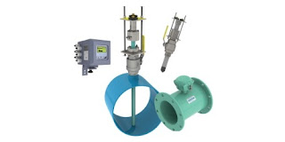
The McCrometer FPI Mag Full Profile Insertion Flow Meter


The McCrometer FPI Mag is ideal for capital or maintenance projects, retrofits and sites never before metered. The unique combination of accuracy, ease of installation, and total cost savings make the FPI Mag the perfect choice for a wide range of Municipal and Industrial Applications.

The FPI Mag has no moving parts and a single-piece design. The multi-electrode water flow sensor contains nothing to wear or break and is generally immune to clogging by sand, grit or other debris. The FPI Mag is available with forward-flow only or bi-directional measurement for line sizes from 4 to 138 inches.

The sensor body is made from heavy-duty 316 stainless steel for maximum structural integrity and is hermetically sealed and protected by NSF certified 3M fusion-bonded epoxy coating.

The FPI Mag is rated for Hazardous Locations:
- Class 1, Division 2, Groups A-D, T5
- Class 2, Zone 2, Groups A-D, T5

For more information on the FPI Mag contact Miller Energy, Inc. Call them at 800-631-5454 or visit their site at https://millerenergy.com.


Industrial Fluid Flow Measurement

Coriolis flow meter
Coriolis flow meters deliver a mass flow measurement
Image courtesy Yokogawa
Fluid flow measurement is commonly employed in many industrial process control operations. Accurate and useful flow measurement can be obtained with the proper application and installation of a flow meter as part of the fluid transfer system.

Industrial flow meters employ differing technologies to directly or indirectly measure gas and liquid flow rates. The selection of an appropriate measurement technology and instrument will be influenced by a number of factors related to the installation and application demands.

Among the many available technologies for fluid flow measurement, vortex flow meters, magnetic flow meters, Coriolis flow meters, and rotameters are among some of the most common found in industry.

Each of the separate technologies have attributes which can make them more suitable to certain applications. Selecting the most appropriate flow measurement technology for an application is one of the initial and crucial steps to designing a well functioning flow measurement system.
Selection criteria, such as fluid temperature, pressure, and velocity will be part of the selection process. Additional considerations include whether the fluid may be abrasive, corrosive, clean or dirty. The state of the fluid, liquid or gas, must also be considered. The desired output, whether volumetric or mass flow, will certainly be an integral part of the criteria.

Selecting the right measurement technology and instrument is not always an easy task, especially since it may be something that you do infrequently. Share your flow measurement challenges and requirements with process instrumentation specialists, leveraging your own knowledge and experience with their product application expertise to save time and develop an effective solution.

Using Brooks Mass Flow Controllers with LabVIEW™

coriolis mass flow controller
Coriolis mass flow controller
Image courtesy Brooks Instrument
Brooks Instrument is the manufacturer of highly accurate and repeatable mass flow controllers. LabVIEW™ develops integrated software for building measurement and control systems used in laboratories, universities, and pilot manufacturing plants. The combination of Brooks MFCs and LabVIEW software provides users a great option for measurment, control, data acquisition and data storage for mass flow.

Listed below are some of the more convenient communication methods to tie Brooks MFCs and LabVIEW™ software together.

Analog Signal Interface

In many situations LabVIEW™ software users also use analog to digital
I/O cards. With analog input cards, users can run their mass flow controllers utilizing a standard 0-5 volt or 4-20 mA analog signaling via LabVIEW™. This is a time-tested, traditional approach and is recommended for applications without the availability of digital control systems.

RS485 Digital Interface

Brooks Instrument mass flow devices configured with RS485 communications (must have the ‘S’ communications option) provide RS485 digital communications via a 15-pin D connector. The RS485 digital signal is passed directly to a computer running LabVIEW™ through a serial RS485 converter. Brooks models GF40, GF80 and SLA Series mass flow controllers are available with the ‘S’ communications option.

Its valuable to note that there is also a free set of VI file for use with LabVIEW from Brooks. These can be loaded directly into the LabVIEW™ application and provide the basics required to create a LabVIEW control interface using the S-Protocol digital command structure. The VI files are available for download from the Brooks Instrument website.

Another communications alternative is using Brook’s Smart DDE (Dynamic Data Exchange) software tool to create links between the LabVIEW™ application and the GF40, GF80 or SLA Series flow, control, and configuration parameters. Additionally, the user can leverage Windows applications (Excel, Word, Access) and programming languages ( C++, C#, Visual Basic) and SCADA programs from suppliers such as Allesco and Millennium Systems International. No knowledge of the mass flow device S-Protocol command structure is required. With Smart DDE, the user gets direct access to the required data fields. While not a complete turnkey option, it greatly reduces the amount of code required to communicate between LabVIEW and the mass flow controller.

DeviceNet Digital Signal Interface

Brooks models GF40, GF80 and SLA, configured for DeviceNet digital communications, can also be controlled via the LabVIEW™ application provided a National Instruments DeviceNet interface card, associated drivers, and software are used. These additional items support the development of application interfaces using LabVIEW™ software for Windows and LabVIEW™ Real-Time.

According to the National Instruments website:
National Instruments DeviceNet for Control interfaces are for applications that manage and control other DeviceNet devices on the network. These interfaces, offered in one-port versions for PCI and PXI, provide full master (scanner) functionality to DeviceNet networks. All NI DeviceNet interfaces include the NI-Industrial Communications for DeviceNet driver software, which features easy access to device data and streamlined explicit messaging. Use a real-time controller such as PXI and NI industrial controllers to create deterministic control applications with the NI LabVIEW Real-Time Module.

Share your mass flow measurement and control challenges with application experts, leveraging your own knowledge and experience with their product application expertise.

Smart Output™ Module For Water System Monitoring

magnetic flowmeter variants
Full bore flanged and insertion style magnetic flowmeters,
with Smart Output™ technology to enhance their functionality.
Image courtesy McCrometer 
Water distribution systems, though mostly invisible to the general public, are highly complex infrastructure arrangements that extend to a very large number of locations throughout a service area. Monitoring the activity and operational health of the distribution system, key to maintaining high levels of efficiency and service, requires measurement instrumentation installed throughout the system.

Magnetic flowmeters are an integral part of water system instrumentation. Their advantages for use in water systems were outlined in a previous article on how magnetic flowmeters work. McCrometer is an innovator in the design and manufacture of magnetic flowmeters for water system flow measurement. Their Smart Output™ technology is available for use with full bore flanged and insertion style flowmeters to provide the information needed for modern water system operation.

  • AC or DC powered versions
  • Compatible with Sensus and Itron smart water networks
  • Enables networking of water meters throughout distribution system
  • Queries, diagnostics, and data transfer can be scheduled or on demand
  • Enables AMR (Automatic Meter Reading) and AMI (Advanced Metering Infrastructure)
The Smart Output™ function is an additional module included as part of the instrument transmitter. 

More information is available from product application specialists, with whom you should share your flow measurement challenges of all types. Leverage your own process knowledge and experience with their product application expertise to develop effective solutions.

Magnetic Flowmeters: Principles and Applications

industrial process measurement instrument magnetic flow meter magmeter volumetric flow transmitter
Magnetic flowmeters are well suited for flow measurement
with conductive fluids.
Image courtesy Yokogawa
Fluid process control operations rely on the operator's ability to accurately determine qualities and quantities of liquid or gaseous materials. In terms of appraising and working with fluids (such as liquids, steam, and gases) the flowmeter is a staple tool, with the simple goal of expressing the delivery of a subject fluid in a quantified manner. Measurement of media flow velocity can be used, along with other inputs, to determine volumetric or mass flow. The magnetic flowmeter, also called a magmeter, is one of several technologies used to measure fluid flow.

In general, magnetic flowmeters are sturdy, reliable devices able to withstand hazardous environments while returning accurate measurements to operators of a wide variety of processes. The magnetic flowmeter has no moving parts. The operational principle of the device is powered by Faraday’s Law, a fundamental scientific principle stating that a voltage will be induced across any conductor moving at a right angle through a magnetic field, with the voltage being proportional to the velocity of the conductor. The principle allows for an inherently hard-to-measure quality of a substance to be expressed via the magmeter. In a magmeter application, the meter produces the magnetic field referred to in Faraday’s Law. The conductor is the fluid. The actual measurement of a magnetic flowmeter is the induced voltage corresponding to fluid velocity. This can be used to determine volumetric flow and mass flow when combined with other measurements.

The magnetic flowmeter technology is not impacted by temperature, pressure, or density of the subject fluid. It is however, necessary to fill the entire cross section of the pipe in order to derive useful volumetric flow measurements. Faraday’s Law relies on conductivity, so the fluid being measured has to be electrically conductive. Many hydrocarbons are not sufficiently conductive for a flow measurement using this method, nor are gases. On the other hand, water and aqueous solutions tend to exhibit sufficient conductivity to apply magmeter technology.

Magmeters apply Faraday’s law by using two charged magnetic coils; fluid passes through the magnetic field produced by the coils. A precise measurement of the voltage generated in the fluid will be proportional to fluid velocity. The relationship between voltage and flow is theoretically a linear expression, yet some outside factors may present barriers and complications in the interaction of the instrument with the subject fluid. These complications include a higher amount of voltage in the liquid being processed, and coupling issues between the signal circuit, power source, and/or connective leads of both an inductive and capacitive nature.

In addition to salient factors such as price, accuracy, ease of use, and the size-scale of the flowmeter in relation to the fluid system, there are multiple reasons why magmeters are the unit of choice for certain applications. They are resistant to corrosion, and can provide accurate measurement of dirty fluids – making them suitable for wastewater measurement. As mentioned, there are no moving parts in a magmeter, keeping maintenance to a minimum. Power requirements are also low. Instruments are available in a wide range of configurations, sizes, and construction materials to accommodate various process installation requirements.

As with all process measurement instruments, proper selection, configuration, and installation are the real keys to a successful project. Share your flow measurement challenges of all types with a process measurement specialist, combining your own process knowledge and experience with their product application expertise to develop an effective solution.

Sometimes the Simple Solution Is the Best

metal tube variable area flowmeter
This metal tube variable area flow meter is reliable,
accurate, and requires little maintenance
Photo courtesy Brooks Instrument
For process control and commercial or industrial applications, there are numerous methods of flow measurement from which to choose. Technologies range from very simple applications of physical principles to deployment of very specialized electronics and sensors. The available range of accuracy, response, and cost is quite broad, with a general expectation that higher cost will deliver better performance and accuracy.

Making the best instrument selection for a flow measurement application should include an assessment of what the operators really need in order to safely and effectively run the process or perform the task related to the measurement of fluid flow. Installing instrumentation with capabilities far beyond what is required is almost certainly a waste of financial resources, but may also have an unexpected impact on operators. Through the generation of data that, while accurate, does not provide any actionable information about process condition, operators can be misled, similar to the occurrence of a false or nuisance alarm. Some applications call for high accuracy, some do not. Define your informational needs and select instruments that will meet those needs.

There is a large array of applications that can be satisfied with simpler, less costly measurement technology. These devices often employ turbines or vanes to produce an indication of flow rate. Incorporated into some of the instruments is a means to visually observe the flowing liquid to verify color and clarity. Simple devices sometimes are intended only to indicate the presence of fluid flow, and whether the flow rate is high or low. Configurations are available that allow insertion into lines under pressure (hot tap) through a full port ball valve. Other variants with combinations of features and capabilities abound.

The selection range is enormous, so define your minimum needs first, then search for a compatible product. Your search can be enhanced by contacting an instrumentation specialist. Combining your process expertise with their broad product knowledge will produce effective solutions.


Primary Flow Elements - Orifice Plate

orifice plate for measuring fluid flow
A simple orifice plate
Courtesy Flow Lin
An orifice plate, at its simplest, is a plate with a machined hole in it. Carefully control the size and shape of the hole, mount the plate in a fluid flow path, measure the difference in fluid pressure between the two sides of the plate, and you have a simple flow measurement setup. The primary flow element is the differential pressure across the orifice. It is the measurement from which flow rate is inferred. The differential pressure is proportional to the square of the flow rate.

An orifice plate is often mounted in a customized holder or flange union that allows removal and inspection of the plate. A holding device also facilitates replacement of a worn orifice plate or insertion of one with a different size orifice to accommodate a change in the process. While the device appears simple, much care is applied to the design and manufacture of orifice plates. The flow data obtained using an orifice plate and differential pressure depend upon well recognized characteristics of the machined opening, plate thickness, and more. With the pressure drop characteristics of the orifice fixed and known, the measuring precision for differential pressure becomes a determining factor in the accuracy of the flow measurement.

There are standards for the dimensional precision of orifice plates that address:

  • Circularity of the bore
  • Flatness
  • Parallelism of the faces
  • Edge sharpness
  • Surface condition
Orifice plates can be effectively "reshaped" by corrosion or by material deposits that may accumulate from the measured fluid. Any distortion of the plate surface or opening has the potential to induce measurable error. This being the case, flow measurement using an orifice plate is best applied with clean fluids.

Certain aspects of the mounting of the orifice plate may also have an impact on its adherence to the calibrated data for the device. Upstream and downstream pipe sections, concentric location of the orifice in the pipe, and location of the pressure measurement taps must be considered.

Properly done, an orifice plate and differential pressure flow measurement setup provides accurate and stable performance. Share your flow measurement challenges of all types with a process measurement specialist, combining your own process knowledge and experience with their product application expertise to develop an effective solution.